The Time Capsule Project (TCP) is a pan-ISSMGE project in which all the member societies, technical committees and other groups contributed review of development of geotechnical engineering in their region and theme since the birth of the ISSMGE in 1936. The contributors are given a total freedom of what and how to present – based on instruction to "consider, the past, present and future in developing their contribution, and can submit on any or all aspect of time and scope they consider most appropriate for their case.” The Department of International Affairs designed and edited the JGS’s contribution by inviting writings from experts within the society on events under four headings; Hardships and Challenges faced by society, Geotechnical Innovation originating from Japan, Projects and Achievements heralding new eras, and Engineers in Union and Action that led to overcoming difficulties. Reviewing the past 100 years, and sharing perspectives of what to come in future on common ground within the society was never an easy task. The limited time window for editing work also meant that each entry had only a minimum description. However, we believe that this TCP is sufficient in reminding later generations of how we in the 2020s viewed the past and what we envisaged for future. We also hope that this little history of Japan’s domestic geotechnical events is illuminating to overseas readers, who might see a whole geotechnical world in this grain of sand.

This TCP output is available in two formats: A static format for printing, and a dynamic HTML format for browsing on screen. The very nature of time capsule (buried and then recovered after years of weathering and endurance) means that the printed version free from any whim of digital ecological change retains its share of importance. It is our wish that this TCP is found in fresh air sometime, hopefully with all the hardships and challenges we list in it having been solved by then.

Kanto earthquake

Kanto earthquake

Kanto earthquake occurred at 11:58, 1 September 1923. It caused the worst damage and loss in many measures in Japan’s natural disaster history, with the death toll reaching 105,000 – by far the largest among other earthquakes in record. Despite the epicenter being some distance away from Tokyo (the exact mechanism is unclear, but the fault is estimated to run in parallel to Sagami Trough, stretching from Kanagawa to the southern tip of Boso Peninsula), most of the casualties (estimated to be some 90 thousands) died of fire that engulfed downtown Tokyo. Most of the seismometers went out of range for the unexpectedly intense vibration, and this has left the exact magnitude and seismic intensity to experts’ guess, but the best estimate of the magnitude is likely to be around Mj=7.9 (Takemura, 2003). The earthquake had decisive influence on the subsequent Japan’s urban planning policy and earthquake research (see also “Early days of soil dynamics Resonant column device, Mononobe-Okabe theory”) – for example, the Earthquake Research Institute, University of Tokyo, was established following the event, and it is still leading Japan’s earthquake research to date. In 1924, immediately after the earthquake, a law was enforced requiring earthquake forces to be considered in building design, and it has evolved into today’s Building Standards Law. In geotechnical context, detailed analysis of building damage in various written records revealed clear site amplification effects in the eastern low land of Tokyo, consistent with local surface geology. Closer to the epicenter, in such places as today’s Odawara, geotechnical disasters included multiple landslides and debris flows that claimed more than 800 fatalities.

Takemura, M. (2003): Kanto Daishinsai. Kajima Institute Publishing, 139p. ISBN4-306-09370-0 C1050

Early days of soil dynamics: Resonant column device, Mononobe-Okabe theory, etc.

Early days of soil dynamics: Resonant column device, Mononobe-Okabe theory, etc.


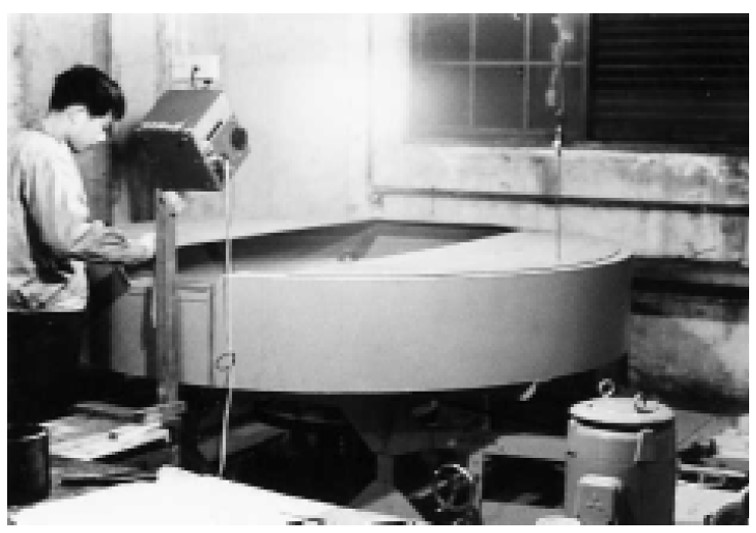
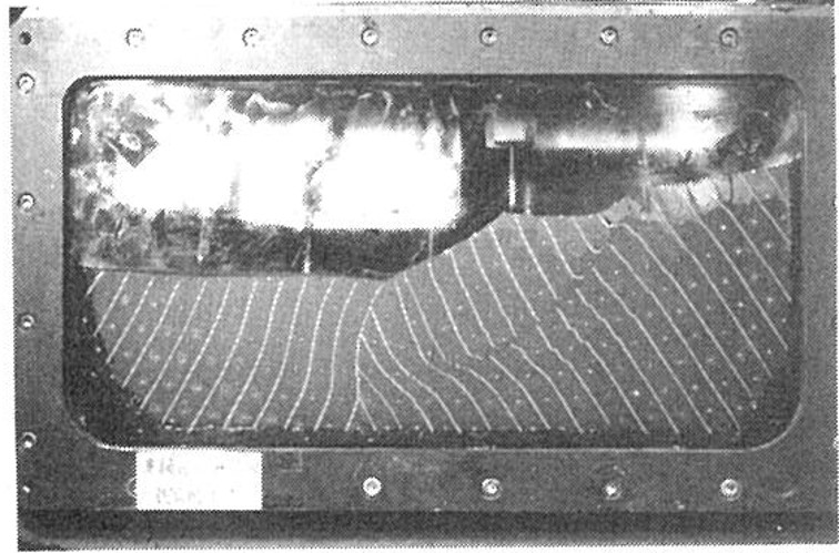
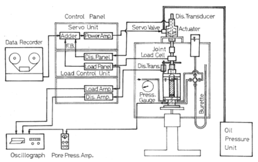
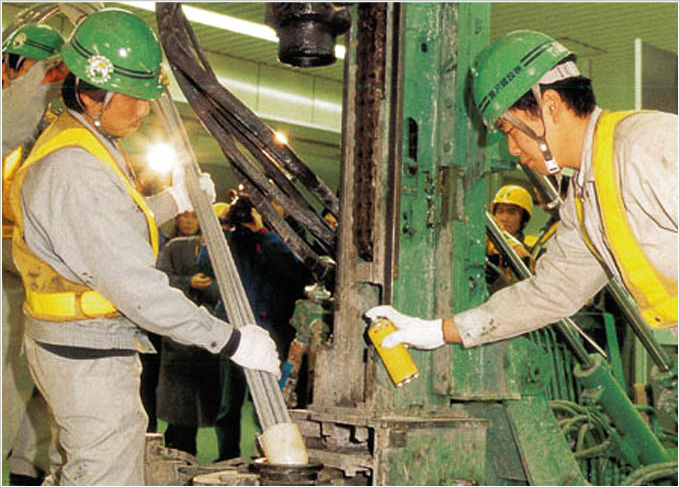
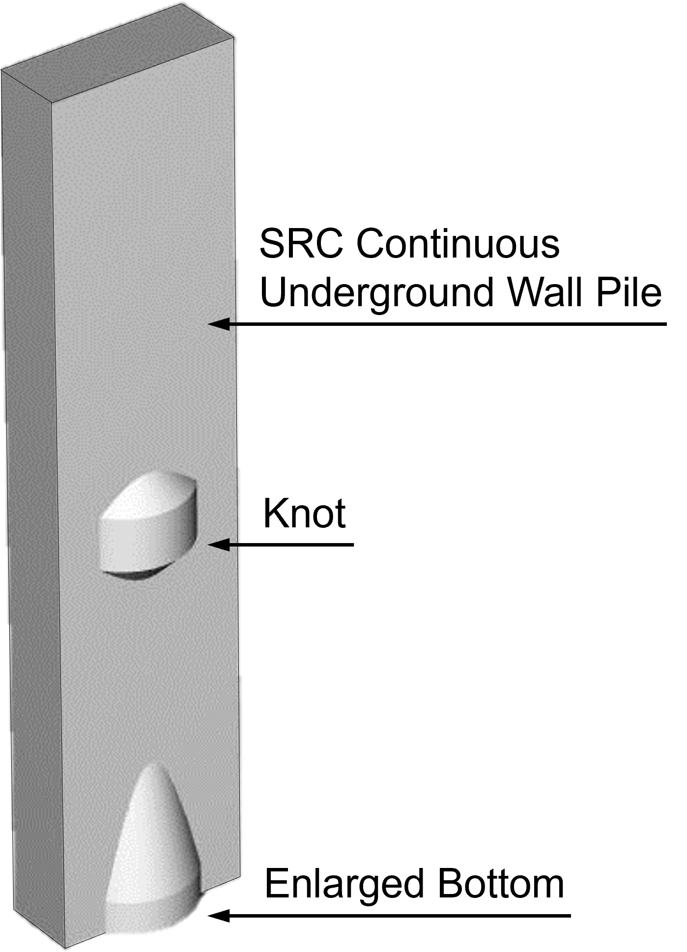
The first resonant column device (Ishimoto & Iida, 1936; © 2021 Earthquake Research Institute, The University of Tokyo.)


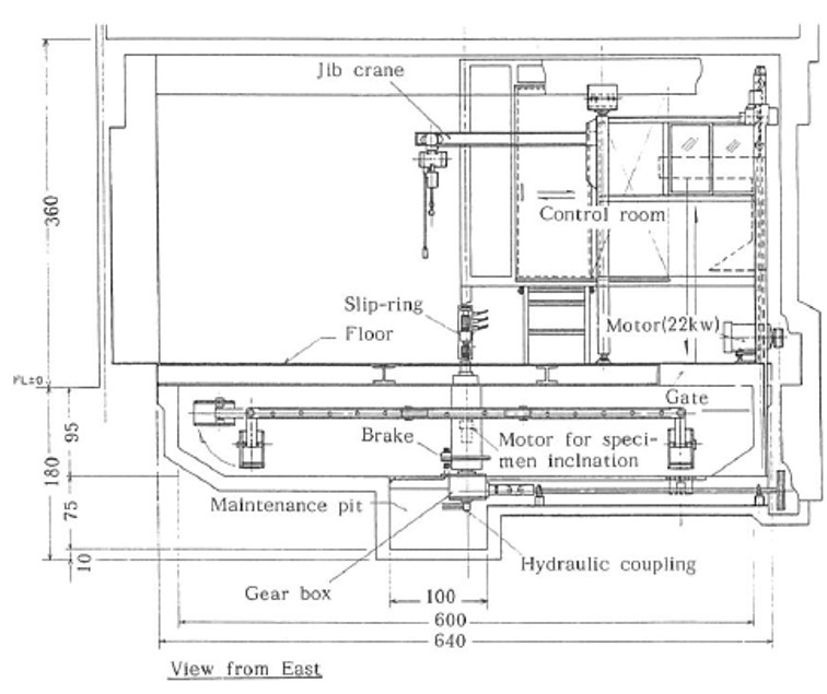
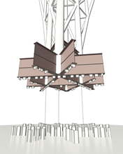
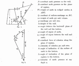
Diagram from Okabe (1924)

Earthquake engineering has always been at the center of civil engineering in Japan, and this was most probably so even before the birth of modern soil mechanics. Some of the innovative ideas from the 1920s and 1930s still influence our daily engineering design and investigation. Specific examples, to which Japan can claim the originality, include resonant column testing and Mononobe-Okabe theory on seismic earth pressure.

The first development of a resonant column device is credited to Dr. Iida and his group in the 1930s (Ishimoto & Iida, 1936; 1937, Iida, 1938), who recognized the importance of what we call ‘site effects’ on amplification of seismic motions and saw a need for obtaining soil stiffness and damping properties dynamically. This innovation directly or indirectly led to blooming of laboratory soil dynamics research in the USA in the 1960s and 1970s, in which the principle of resonant column testing was adopted in various machine designs, and eventually to stipulation in ASTM D4015. It is refreshingly impressive to see that Iida’s papers, published in bulletins of Earthquake Research institute, University of Tokyo, are all written in English.

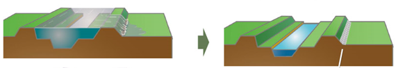
Mononobe-Okabe theory on seismic earth pressure originates from a suite of papers that appeared in the 1920s, authored independently by Dr. Nagaho Mononobe (Mononobe & Matsuo, 1929) and Dr. Sabro (in his own spelling) Okabe (Okabe, 1924), both working for the Department of Home Affairs (Naimushō) of Japanese Government. The theory is based on limit equilibrium with pseudo-static approach to the seismic inertia force. Even today, the theory has a place in many official design codes in Japan and elsewhere.

Ishimoto, M. & Iida, K. (1936): Determination of elastic constants of soils by means of vibration methods. Part 1. Young’s modulus. Bulletin of Earthquake Research Institute, University of Tokyo 14 632-657.
Ishimoto, M. & Iida, K. (1937): Determination of elastic constants of soils by means of vibration methods. Part 2. Modulus of rigidity and Poisson’s ratio. Bulletin of Earthquake Research Institute, University of Tokyo 15 67-85.
Iida, K. (1938): The velocity of elastic waves in sand. Bulletin of Earthquake Research Institute, University of Tokyo 16 131-145.
Mononobe, N. & Matsuo, H. (1929): On the determination of earth pressure during earthquake. Proceedings of World Engineering Conference, Tokyo, 9 177-185.
Okabe, S. (1924): General theory on earth pressure and seismic stability of retaining wall and dam. Proceedings of JSCE 10 (6) 1277-1330.


More:
See the early papers on ERI website: https://www.eri.u-tokyo.ac.jp/en/publication/

Tokyo metro: Ginza Line

Tokyo metro: Ginza Line


The crossing section of the open-cut tunnel: Steel stile structure tunnel (between Kanda Station and Mitsukoshimae Station) (Photo provided by Tokyo Metro Co. Ltd.)


The crossing section of the mountain tunnel: Kandasudacho Tunnel (between Suehirochou Station and Kanda Station) (Photo provided by Tokyo Metro Co. Ltd.)

In the early 20th century, industrial development of Japan made it impossible for streetcars alone to keep up with traffic demand of Tokyo, and subway construction was planned to relieve traffic congestion. The construction of the Ginza Line started in 1925, and the 2.2km line between Asakusa and Ueno opened in 1927. This was the first subway in the Orient. Thereafter, the entire 14.3 km line between Asakusa and Shibuya opened in 1939. The Ginza Line connects key locations of commercial activity in Tokyo such as Ueno, Kanda, Nihonbashi, Ginza, Shinbashi, Toranomon, Akasaka, and Shibuya. Almost the entire line consists of open-cut tunnels, and as the first subway, the subway tunnels are shallow with about 16 meters earth cover.

The construction was initially carried out under the direction by Rudolf Briske, an engineer from Siemens AG of Germany. The open-cut tunnel between Asakusa and Shinbashi was constructed using steel stile structure with slabs placed between H-shaped steel frames at regular intervals, which were widely used in Europe and the United States at the time. The Kanda River Bottom Tunnel, the first river bottom tunnel in Japan, is approximately 50m long and 9.4 m wide. Prior to the bridge construction, the tunnel was first built at the bottom of the river, and then the Manse Bridge was built over it. Since the tunnel sections supporting the abutments were subjected to greater loads than the other sections, bottoms of the tunnel were embedded to the ground to resist the horizontal force of the abutment load. The Kandasudacho Tunnel was constructed using the mountain tunneling method which is a non-open-cut method because the tunnel was located directly under private houses and the soil cover was quite deep. This arched tunnel has unreinforced concrete lining, approximately 130 m long and 11 m wide. At first, some people thought, "Tokyo is not suitable for a subway because of the softness of the ground. However, the line was successfully completed because of introducing new technologies.

Although 95 years have passed since its opening, it is confirmed from the results of periodic inspections that the structure remains in sound condition.

Wushantou Dam and Chianan Irrigation System

Wushantou Dam and Chianan Irrigation System


Wushantou Dam (Photo by Dr. Ikuo Towhata)


Spillway (Photo by Dr. Ikuo Towhata)

In early 20th Century, the Taiwan Island was considered a promising food basket and several agricultural development projects were planned. The first irrigation project was completed in 1924 in the Taoyuan area in the north for which a reservoir and, in total, 282 km of water channels were constructed in order to produce 220 km2 of rice field. Then, the attention was paid to the south where almost 1500 km2 of new rice field was expected.

The "Chianan Irrigation" project in the south started in 1920 and was completed in 1930. While the irrigation infrastructure consisted of water intake, tunnels, reservoir, and distribution channels, the engineering difficulties were encountered in the tunnelling and the construction of an earth dam. The tunnel was 3,078 m long and its diameter was 5 m, which was considered big in those days. In spite of troubles such as explosion of natural gas and mud swelling in the tunnel, the tunneling was completed in 1924.

The most remarkable achievement of the project was the construction of the Wushantou earth dam that was 1,273 m long and 56 m high, enabling the water storage of 150 million m3 in the reservoir. The major feature herein was the innovative introduction of huge construction machines for semi-hydraulic filling by which a less pervious core and more pervious outer zones were made. The total length of the irrigation channel was 16,000 km.

Although not well known, the water resource available for this irrigation project was not enough to provide water for rice agriculture in the entire service area. To overcome this problem, it was decided to introduce the three-year crop rotation in place of simply shrinking the service area, because it was preferred to provide a greater number of farmers with water. Every year, one third of farmers spent more water on rice agriculture and others got less water for sugar cane and other crops. The point here is that the irrigation project consisted not only of construction of infrastructure but also of the agricultural policy.

Last but not least, the success of this big agricultural project in Taiwan was made possible by the enthusiasm of the leading civil engineer, Mr. Yoichi Hatta.

Furukawa, K. (1989): Life of Yoichi Hatta, Father of Chianan Irrigation System and Lover of Taiwan. Publ. Aoba Books, Tokyo (in Japanese).
Wu, W. (2000): On agricultural soil improvement in Taiwan and contribution to it by Yoichi Hatta. Bulletin of Historical Research, National Taiwan Normal University 28 159-170 (in Chinese).

JCSMFE established to join ISSMFE

Renamed to JSSMFE

Soils and Foundations launched

Soils and Foundations launched


Cover page of the first issue of Soil and Foundation


Contents page of the first issue of Soil and Foundation

In April, 1960, the first issue of Soil and Foundation (renamed into “Soils and Foundations” in 1968 in anticipation of more emphasis to be put on papers dealing with practices rather than theory) was published. According to its foreword, publication of this English language journal was contemplated as one of the activities to commemorate the tenth anniversary of the founding of the Japanese Society of Soil Mechanics and Foundation Engineering (renamed into “Japanese Geotechnical Society” in 1995).

The first chair of the editorial committee was Prof. T. Mogami. Reportedly, there had been a great deal of groundwork behind the publication, including the collection of good quality papers and their translation into English. At that time, publication of a technical English journal in Japan was a bold attempt, considering the lack of experience of Japanese geotechnical engineers in writing English papers, and the lack of financial resources.

The first special issue was published in 1966 on the 1964 Niigata Earthquake, which received enthusiastic response from abroad, and contributed to making the journal better known in the geotechnical engineering community in the world.

The publication was meant to be biannual at first, and then it became quarterly and bi-monthly in 1972 and 1999, respectively. An electric journal service was introduced in 2010, and from January, 2020, Soils and Foundations is a full open access journal.


More:
Yoshimi, Y. (1999): Soils and Foundations during the 1960s. Soils and Foundations 39 (5) 5-6.
Ishihara, K. (2010): Retrospective overview on developments of “Soils and Foundations”. Soils and Foundations 50 (6) 777-783. https://doi.org/10.3208/sandf.50.777

Fukui earthquake

Kanmon Tunnel

Urban ground settlement

Urban ground settlement


Areas suffering ground settlement (black fill) and those with signs of it (white marker) in 1974 (Kutara, 1975)


Ground settlement in Osaka (Hashimoto, 2008)

The urban ground settlement had already been a chronic problem in large cities in Japan by the war era of the 1940s, possibly starting even before Taisho Era (the 1910s). The mechanism causing the problem was not clear until the wartime interruption of industrial activities led to a temporary half of ground water use, and the subsequent slowing down of the ground settlement proved that the ground water level lowering was the culprit. The problem resumed with the post-war industrial use of the ground water. In such highly urban districts as Marunouchi and Hibiya in Tokyo, ground water use by office buildings caused local settlement too, as revealed by pile exposure. As the ground settlement was most significant in low-lying areas, the cities saw a share of their land going subsea levels – a factor that may have aggravated the Nagoya inundation by the high tide during 1959 Ise Bay Typhoon. Waterfront areas also suffered salinization of the ground water. A law regulating the ground water was enforced in the 1960s, and the large cities including Tokyo and Osaka were put under its control. It was around the end of the 1970s that the urban ground settlement eventually ceased. By then, the eastern lowland of Tokyo and western Osaka had suffered up to 4.5m (the maximum value observed at Minamisuna, Kōtō Ward) and 3m of ground settlement, respectively. The ground water level recovery after the 1970s have led to ground lifting (see also “ground lifting”) and distress in underground structures built in more modern time.

The retrospective summaries of the urban ground settlement problems are abundant – see, for example, Endo et al. (2001) for Tokyo and Hashimoto (2008) for Osaka.

Endo, T., Kawashima, S. & Kawai, M. (2001): Historical review of development of land subsidence and its cease in Shitamachi Lowland, Tokyo. Journal of the Japan Society of Engineering Geology 42 (2) 74-87. (in Japanese; abstract available in English)
Hashimoto, T. (2008): Ground water and ground subsidence. The 50th Anniversary volume of Kansai Branch of JGS 69-74.
Kutara, K. (1975): Chikasui mondai no kadai to jittai. Tuchi to Kiso (Bulletin of the JSSMFE) 23 (8) 83-85.

Ise Bay Typhoon

Tokyo Metro: Marunouchi Line

Tokyo Metro: Marunouchi Line


Roof shield (between Kokkaigijidoumae Station and Akasakamitsuke Station) (Photo provided by Tokyo Metro Co. Ltd.)


Pneumatic caisson method (Uchisaiwaichou near Hibiya park between Empire Hotel and Takarazuka Theater) (Photo provided by Tokyo Metro Co. Ltd.)

The Marunouchi Line was the first subway line opened in Tokyo after World War II. The construction between Akasaka-mitsuke and Yotsuya-mitsuke was started in 1942. However, it was stopped in 1944 after placing only sheet piles because of shortage of materials due to the War. The construction work was restarted in 1951 and the 6.4 km section between Ikebukuro and Ochanomizu was opened in 1954. The line was then successively extended to Ikebukuro, Otemachi, Tokyo, and Shinjuku in 1959, and to Ogikubo in 1962, covering a distance of 27.4 km. The Marunouchi Line with a U-shape connects major parts of Tokyo: Ikebukuro, Ochanomizu, Tokyo Station, Ginza, Kasumigaseki, Akasaka, Yotsuya, and Shinjuku. Because the line is situated under richly undulating terrains, the line has several above-ground sections. The ground was very soft in some areas, making construction difficult at the time. In addition, in preparation for the future increase in the construction of new subway lines, the construction was carried out by actively introducing the latest technologies of the time, such as ready-mixed concrete, the roof shield method, the pneumatic caisson method, and the Ikos method. A few details about these technologies are presented below. Because the RC rigid-frame structure was applied to construct the open-cut tunnel, a large amount of concrete was required and ready-mixed concrete was used for the first time in Japan. Because the ground was very soft, and noise and traffic problems were severe in some sections, the tunnels of the sections were constructed using the pneumatic caisson method. The roof shield method was also used in sections where the overburden was large and the groundwater table was high in sand ground. In this method, a semicircular steel frame with the size of the tunnel is pushed while digging under it without collapsing, and concrete is placed around the tunnel. In addition, test construction by the Ikos method which is continuous underground wall construction method in the early days was conducted. Instead of using sheet piles, a vertical shaft filled with bentonite mud slurry was excavated, steel cages were installed, and concrete was poured from the bottom to replace the mud slurry and install underground walls. In this section, continuous underground walls are also used combinedly as temporary and permanent walls for the purpose of cost reduction. Although about 70 years have passed since its opening, periodic inspections have shown no major problems with the structure.

Sakuma Dam

Tokyo Tower

Kurobe Dam

Modern ground improvement technologies

Modern ground improvement technologies


Sand drain method in Keiyo National Highway, in 1958 (Photo by Sanshin Corporation)


Vibro flotation method in Nagoya port, in 1959 (Photo by Sanshin Corporation)

Before the war, most of the ground improvement methods in Japan were replacement methods and preloading method. After the war, in the 1950s, vertical drain methods, including the sand drain method and the cardboard drain method, were introduced. Subsequently, the vibro flotation method and the chemical injection method were introduced. The following are examples of the ground improvement method practicalized in the 1950s. The first photograph shows a photograph of the sand drain method implemented in the Keiyo National Highway in 1958. The sand drain method penetrates a casing pipe into soft ground, pulling it out while discharging the sand in the pipe, and setting a large number of vertical sand piles into the ground to shorten the drainage distance and promote consolidation. The second photograph shows the vibro flotation method implemented at Nagoya Port in 1959. The vibro flotation method improves the ground by penetrating a rod-shaped vibrating body called a vibro flot into loose sand ground while jetting water, compacting the ground with water and vibration, and filling the voids with gravel.

Following the drain and compaction methods, admixture stabilization methods, in particular deep mixing methods, were invented in the 1960s. They originated by adopting lime aggregates as stabilizer, and then evolved into Cement Deep Mixing (CDM) method using cement slurry. This was a pioneering development in the world, while Sweden concurrently developed similar techniques but based on lime and cement powder as stabilizer. Both streaks of techniques are now widely adopted in Japan.


More:
Okumura, T. (1999): Historical development of soil improvement works in Japan. Jiban to Kensetsu 17 (1) 1-8. http://jgschugoku.jp/asset/00032/GE/Vol17/ge_vol17_01.pdf

2nd ARC, Tokyo

JGS Awards launched

Niigata earthquake

Niigata earthquake


Liquefaction-induced tilting of apartment buildings in Kawagishi-cho, Niigata


Ongoing water ejection in front of the terminal building of the Niigata Airport (still photograph captured from the motion picture by Mr. F. Yuminamochi)

The Niigata earthquake of Mw=7.6 took place on June 16th, 1964, in Japan. This earthquake was one of the earliest seismic events that affected built structures in modern urban environment. The induced damage in soft alluvial subsoil and embedded lifelines verified the problems in modern cities for the first time, although their likelihood had been pointed out by speculation of experts. Those problems are still important nowadays in disaster mitigation planning of mega cities. Among the problems, liquefaction of loose sandy ground is the most important and destroyed modern buildings, lifelines and revetment walls in Niigata. In response to those disasters, extensive research on liquefaction started immediately after the Niigata earthquake. It is a great surprise that, at this very beginning of the liquefaction research, invaluable knowledge was obtained such as motion picture of ongoing water ejection in the Niigata Airport where a professional photographer, Mr. F. Yuminamochi, was ready to take off by a small airplane for a photographing mission and he immediately changed his target to recording of ongoing liquefaction. This motion picture has been universally studied since then by many liquefaction experts and students. Another unforgettable event was the tilting of RC apartment buildings in Kawagishi-cho site in Niigata. It was miraculous that a strong-motion record was obtained in the basement of the apartment building and the effects of subsoil liquefaction on the surface shaking (weaker amplitude of acceleration as well as elongated shaking period) were visually verified. Furthermore, the fragility of embedded lifelines undergoing liquefaction, the effect of lateral displacement of liquefied subsoil on revetment walls and pile foundations, and the coseismic risk of fire in chemical plants were recognized and have been seriously considered in many design codes worldwide. The city also suffered tsunami inundation. In this particular event, however, the tsunami water at least helped extinguish the fire caused by the earthquake in the commercial area.

Geotechnical centrifuge

Geotechnical centrifuge


Prof. Masato Mikasa (courtesy of Prof. Akihiko Oshima, Osaka City University)


Mark 1 centrifuge for self-weight consolidation in Osaka City University (Mikasa, 1984)


Failure of remolded and consolidated clay (after the test; failed at 124.6 g) (Mikasa, 1984)


Mark 5 centrifuge in Osaka City University (Mikasa, 1984)

To properly simulate prototype behavior through observing scaled model response, both the geometric and mechanical similarities should be implemented all at once. For model tests with soils whose stress - strain relationship strongly depends on the applied confining pressure, it is important to give a model the same level of confining pressure as it is in the real field. The idea of applying centrifugal acceleration to a scaled model was proposed by Phillip in 1869 and model tests were reported by Bucky in 1931 (the 1st generation) (Kimura & Kusakabe, 1987).

In January 1965, Prof. Masato Mikasa in Osaka City University developed the first geotechnical centrifuge, Mark 1, in Japan, whose radius was 1.00 m, and maximum centrifugal acceleration was 200 G (G is the acceleration due to gravity). He conducted a series of experiments for consolidation of clay. In the same year, Prof. Schofield developed the one in Cambridge University. In 1969, second centrifuge in Japan was developed in Tokyo Institute of Technology. Range of earlier geotechnical centrifuge studies was limited to problems governed by self-weight of soils, such as consolidation and slope stability (the 2nd generation).

In 1970s (the 3rd generation), application of the geotechnical centrifuge modeling to various and complex problems in geotechnical field started with the rapid development of computer technologies. In 1979, Port and Harbour Research Institute, Ministry of Transport in Japan at the time, built a large centrifuge with the arm length of r=4 m. In UK, in 1971 Manchester University built one with r=3m and in 1973 Cambridge University with r=4 m. In the late 1970s (the 4th generation), model testing for dynamic problems including soil liquefaction become one of the major topics on physical modelling. In 1984, Toyo Construction Co. LTD., developed the first geotechnical centrifuge owned by a private company in the world.

Mikasa, M. (1984): Two decades of centrifugal testing at Osaka City University. Proceedings of International Symposium on Geotechnical Centrifuge Model Testing, Tokyo 43-52.
Kimura, T. & Kusakabe, O. (1987): Centrifugal model testing: 2. Introduction. Tsuchi to Kiso, Japanese Society of Soil Mechanics and Foundation Engineering 35 (11) 68-74 (in Japanese).

Artificial ground freezing

Artificial ground freezing


The first application of AGF in Japan: Osaka in 1962 (© 2021 Seiken, Co. Ltd.)


The first application of AGF in Japan: Cross-section (© 2021 Seiken, Co. Ltd.)


Application of AGF to offshore shaft in Tokyo Bay Aqua-Line Expressway project (© 2021 Seiken, Co. Ltd.)

The first application of Artificial Ground Freezing (AGF) to modern underground construction in Japan was for a buried water pipeline project in Osaka in 1962. The technique adopted for this particular project was developed originally in Japan (by Seiken Co. Ltd. and Kyoto University), and with more than 600 completed projects with AGF, Japan has been leading the world in its development. Through the series of International Symposia on Ground Freezing starting from 1978, Japanese AGF technologies and their applications were widely known to the world. In addition to the execution techniques involved in freezing, AGF requires sophisticated predictive method for ground movement and stability, especially caused by frost expansion and frost heave. The coupling of pore water and heat flows can lead to excessive deformation. Motivated also by a suite of underground LNG tank projects in the 1970s, analytical and numerical methods and models have been invented. Among these is Takashi’s formular for frost heave (Takashi et al., 1974), which is still widely used not only in AGF but in cold-region ground surface frost heave problems. The formular eventually led to standardization of frost heave testing as JGS 0171-2009. AGF was brought to fore in engineering community a few times in later years – it was adopted in Tunnel Boring Machine (TBM) launching from shafts, as well as in TBM joints, in Tokyo Bay Aqua-Line Expressway in the 1990s (see also “Tokyo Bay Aqua-Line Expressway”), and in Fukushima Daiichi Nuclear Power Plant site to form underground cut-off walls against contaminated underground water. Between these years, notable technical progress was seen, for example, in the Metropolitan Expressway Inner Ring Road Shinjuku Route tunnel in the 2000s, where ground stabilization and water-cut were achieved only with ground freezing around pipe-roof. Application to some high-profile projects, including Tokyo Gaikan Expressway (see also “Tokyo Gaikan Expressway”), is in plan. A recent report by Akagawa (2021) overviews the history of ground freezing in Japan in research and in engineering perspectives.

Takashi, T., Masuda, M. & Yamamoto, H. (1974): Experimental study on the influence of freezing speed upon frost heave ratio of soil under constant effective stress. Seppyo 36 (2) 49-68. (in Japanese, with English abstract)
Akagawa, S. (2021): Systematic survey on frozen ground engineering technology. Survey Reports on the Systemization of Technologies Vol. 30, Center of the History of Japanese Industrial Technology, National Museum of Nature and Science. (in Japanese, with English abstract) http://sts.kahaku.go.jp/diversity/document/system/pdf/120.pdf

Tokaido Shinkansen (Bullet train)

Tokaido Shinkansen (Bullet train)

Expressways:

Expressways:

Nagoya-Hyogo (Meishin),
Tokyo-Nagoya (Tomei)

Nagoya-Hyogo (Meishin),
Tokyo-Nagoya (Tomei)


Construction of drainage work in Amagasaki test embankment (Photo provided by NEXCO EAST Technical Center)


Relationship between SPT-N value, WSW and NSW (Figure from JGS Standards book “Geotechnical and Geoenvironmental Investigation Methods”)


Scrape dozers used in Tomei Expressway (Photo provided by NEXCO EAST)

The Meishin Expressway and the Tōmei Expressway were built in the 1960s as Japan's first intercity expressways. The construction of both expressways was funded partially by loans from the World Bank. The Meishin Expressway cost about 116.4 billion yen to build and the Tomei Expressway cost 342.5 billion yen. The Meishin Expressway was completed in 1965, and the Tomei Expressway in 1969.

The Meishin Expressway has a total length of 189 km from Komaki City, Aichi Prefecture to Nishinomiya City, Hyogo Prefecture. The total volume of earthwork was about 28 million m3. Of this, 71 km from the Amagasaki Interchange to the Ritto Interchange was opened in July 1963 as Japan's first intercity expressway. The design and construction were carried out with reference to the latest geotechnical engineering at that time and literature from other countries. One of the characteristics of the project is that the accuracy of consolidation theory in soil mechanics was investigated by using test embankments in the Amagasaki, Otokuni and Ogaki districts to see if it could be used in practice. The results showed that the strength of the soil was increased due to drainage, whereas no clear difference in the rate of settlement, i.e. acceleration of settlement, was observed. Therefore, drainage work was not used in the Ogaki area. In addition, based on the results of many geotechnical surveys conducted for the Meishin Expressway, the relationship between SPT-N value, WSW and NSW was established. It is still widely used in practice today.

The Tomei Expressway has a total length of 347 km from Setagaya-ku, Tokyo to Komaki City, Aichi Prefecture. One of the main features of the project was the handling of Kanto loam (volcanic ash soil), which was 17 million m3, about 1/4 of the total earthwork volume. In the past, this soil was classified as waste soil in road construction. To overcome this issue, the following attempts were made: use of swamp bulldozers with a ground pressure as low as 3 kgf/m3 (300 kN/m2) and scrape dozers; use of air content for compaction control; and the use of filter layers to dissipate excess pore water pressure generated during embankment construction. These attempts formed the basis of construction methods in Japan for volcanic ash (cohesive) soil with a high water content.

Metropolitan Expressway

Metropolitan Expressway


Towing of Haneda Tunnel (Photo provided by Metropolitan Expressway Company Limited)


Cross-section of Route 3 structure around Roppongi (Image provided by Metropolitan Expressway Company Limited)

Metropolitan Expressway (SHUTOKO) is a system of urban expressways at the core of the road network covering greater Tokyo area. A total length of 327km is in service, carrying a daily traffic of about a million vehicles as of 2022. The main construction stages involved the inner circular route and radial route (1962-1970), connection to intercity expressways (1971-1988) and further development of the network (since 1989 onwards). Of these, the connection of SHUTOKO Route 3 (Shibuya Route) to Tomei Expressway was a milestone development.

The main developments in the early 1960s were closely related to the 1964 Tokyo Olympics. A new 33km-long route connected Haneda Airport (Tokyo International Airport) to Japan National Stadium and the Olympic villages in Jingu-Gaien, Yoyogi and Shinjuku areas. Metropolitan Expressway boasts some of the most advanced geotechnical engineering achievements at the time. One of the featured structures in this route is Haneda Tunnel, adopted due to the height restriction to newly built structures around the airport. Haneda Tunnel has a hybrid structure, with 300m of underwater (immersed) section, 50m of caisson section and 200m of cut-and-cover section. This was only the second project involving immersed tunnelling in Japan. In the cut-and-cover section, the most updated geotechnical analysis and ground improvement techniques against heaving were adopted. The late 1960s saw completion of the inner circluar route and development of connection to Kanagawa sections and the intercity expressways. Notable structures include elevated SHUTOKO Route 3 (Shibuya Route) around Roppongi, which spanned over Tokyo Metro Hibiya Line by constructing underground beams. 2.4m-diameter deep bored piles were installed to support the heavy underground beams for this section, while the other sections adopted 1m-diameter cast-in-place piles.


More:
Japan Civil engineering Consultants Association (JCCA) Website:
https://www.jcca.or.jp/infra70/wp-content/uploads/2021/05/PJNO21.pdf

Liquefaction and dynamic laboratory testing

Liquefaction and dynamic laboratory testing


Early cyclic triaxial apparatus in Japan (Ishihara & Yasuda, 1972)


Liquefaction curve of Niigata sand and else (Ishihara & Yasuda, 1975)

Niigata earthquake and Alaska earthquake in 1964 (see also “Niigata earthquake”) inspired modern liquefaction research in Japan and the US. Seed and Lee (1966) may be the first to adopt triaxial apparatus for liquefaction testing by allowing cyclic loading. Not much later, similar development was seen in Japan, involving cyclic triaxial testing (Ishihara & Yasuda, 1972), and cyclic torsion shear testing (Ishihara & Li, 1972; Ishihara & Yasuda, 1975). After being adopted for research purposes, the cyclic triaxial testing for obtaining liquefaction resistance was eventually standardized as JGS 0541 (see also “JGS Standards”), while standardization of cyclic torsion shear testing is still on agenda as of 2021. There were some attempts in the 1960s-1970s to adopt different types of apparatus, such as ring simple shear device (e.g. Yoshimi & Oh-oka, 1973), but they remained mostly in the research sphere up to the present. In addition to liquefaction testing, cyclic torsion shear testing for obtaining dynamic properties of soils (in particular, the shear modulus, G, and the damping ratio, h) has also been standardized as JGS 0543.

Ishihara, K. & Li, S.-I. (1972): Liquefaction of saturated sand in triaxial torsion shear test. Soils and Foundations 12 (2) 19-39.
Ishihara, K. & Yasuda, S. (1972): Sand liquefaction due to irregular excitation. Soils and Foundations 12 (4) 65-77.
Ishihara, K. & Yasuda, S. (1975): Sand liquefaction in hollow cylinder torsion under irregular excitation. Soils and Foundations 15 (1) 45-59.
Seed, H. B. & Lee, K. L. (1966): Liquefaction of saturated sands during cyclic loading. Proceedings of ASCE, SM6, 105-134.
Yoshimi, Y. & Oh-oka, H. (1973): A ring torsion apparatus for simple shear tests. Proceedings of the 8th ICSMFE 1 501-506.

Earth pressure balance TBM

Earth pressure balance TBM


Concept of earth pressure balance TBM (Image by Shield Tunneling Association of Japan)


TBM used for construction of the railway tunnel crossing the Bosporus Straits (Imaishi et. al., 2014; Photo by Taisei Corporation)

The first application of the shield tunnelling method was for the tunnel crossing the Thames River in 1825 in London. Since then, this construction method has been improved significantly to become one of the most effective methods of tunnel constructions, especially for the tunnels in urban areas and for the crossing tunnels beneath straits/rivers/seas.

The history of the shield tunnels in Japan was initiated by the trial applications to the tunnels at Oriwatari Tunnel in Akita Prefecture and Tanna Tunnel in Shizuoka Prefecture in early 1920s. The first full application was then in the late 1930s to the construction of the Kanmon Railway Tunnel, which was the first undersea tunnel in Japan, crossing under the Kanmon Straits. The early-stage shield tunnelling machine was classified as an ‘open face type’ machine. Although this type allows workers for direct observation of the excavating ground, the air inside the machine often needs to be pressurized to keep the tunnel face stabilized. The open face type shield is not always fully applicable especially to the tunnels in very soft/loose grounds or/and complicated layered grounds, which are very common in Japan.

To cope with the above typical Japanese ground conditions, new type of the shield tunnelling machines have been developed since early 1970s, which is classified as ‘closed face type’. The machine front is closed by the chamber filled with the pressurized mud water or plastic fluidized excavated soil to assure the stabilization of the excavated ground. The closed face type machine is broadly divided into two categories, i.e., earth pressure type and mud water type according to the materials and conditions filled in the chamber. In principle, the pressure in the chamber is controlled to balance with the sum of the earth pressure and the water pressure at front during excavation, which is the basic concept of the earth pressure balance Tunnel Boring Machine.

Much securer and safer tunnel constructions have been achieved by the new system, which allow for constructions of the tunnels with diameter more than 10m, even in very difficult ground conditions. Tokyo Bay Aqua-line Tunnel (diameter d=14.1m) and the Tokyo Outer Ring Road Tunnel (d=16.1m) are typical applications to large-diameter tunnels in Japan. The system is also exported to overseas, for example, for the construction of the railway tunnel crossing the Bosporus Straits (d=7.6m), and Eurotunnel, i.e., the Dover Straits undersea tunnel (d=8.8 m).

It should also be empathized that this technology was selected as one of the 100 Japanese Innovations after the War by the Japanese Institute of Invention and Innovation (http://koueki.jiii.or.jp/innovation100/innovation.php, in Japanese).

Imaishi, T., Inazumi, N., Yugami, S. & Ando, A. (2014): Construction of slurry type TBM tunnel, Kisoko (The Foundation Engineering & Equipment) 42 (1) 69-74. (in Japanese)

9th ICSMFE, Tokyo

Urban groundwater recovery and ground lifting

Urban groundwater recovery and ground lifting


Installation of anchors from Tokyo Station platform (Photo from KTB Association: http://www.ktb-kyoukai.jp/civil/cases/01.html)

The urban areas in Japan suffered significant ground settlement in the 20th century (see also “Urban ground settlement”). The settlement was largely under control by the end of the 1970s, as the ground water use was tightly restricted by law. However, this has led the problem to the opposite direction – the ground water recovery and ground lifting. The ground water recovery meant that underground work was more difficult due to the increased water pressure. An accident involving significant water and soil leak during excavation to 25m depth adjacent to Osaka Station typifies the problems (Shibata 1988; Hashimoto, 2008). Existing underground structures were also subject to distress from the rising ground water level. Notable examples include Sobu and Tokyo Tunnels along JR Yokosuka – Sobu Lines, which suffered water leaks reaching 4,500 m3/day, almost immediately after being put to service in the 1970s. Underground stations including Ueno and Tokyo stations were subject to uplifting forces. Iron ingots were placed on Ueno Station in the 1990s, and then the whole station box was tied to deeper strata by ground anchors (e.g. Oshima, 2020). Similar countermeasures were applied to Tokyo Station, where 130 ground anchors were installed from the station platform down to 18m depth.

The ground lifting due to the ground water recovery was modest in comparison to the ground preceding settlement, with a rate of 4 cm at maximum, and more typically 1-2cm, from the end of the 1970s. Endo et al. (2001) estimates the eventual lifting to be around 2% of the preceding settlement in Tokyo.

Endo, T., Kawashima, S. & Kawai, M. (2001): Historical review of development of land subsidence and its cease in Shitamachi Lowland, Tokyo. Journal of the Japan Society of Engineering Geology 42 (2) 74-87. (in Japanese; abstract available in English)
Hashimoto, T. (2008): Ground water and ground subsidence. The 50th Anniversary volume of Kansai Branch of JGS 69-74.
Oshima, H. (2020): Tunnel and groundwater - My knowledge from the field -. Journal of Groundwater Hydrology 62 (2) 257-281. (in Japanese; abstract available in English)
Shibata, T. (1988): Kansai ni okeru jibanmondai no nakakara. The 30th Anniversary volume of Kansai Branch of JSSMGE 99-104.

Elasto-plastic soil modelling

Elasto-plastic soil modelling


State surface of Cam-clay model

Soils consist of solid grains and voids which are filled with water and air, or either of them. The total stress is recognized as a sum of the pressure of pore fluids and the effective stress brought by the solid skeleton. Since the behavior of the solid phase is to be interpreted as a result of effective stresses exerted to the soil, the constitutive model which describes the stress-strain relationship is based on the effective stress.

Though the plasticity theory of metals precedes that of soils, the mechanical behavior specific to the soil is dilation unlike the metal, which implies the plastic volume change due to shearing. The dilation in granular materials is caused by individual grains riding up over each other in order to accommodate shear strains. However, the dilation (or sometimes the contraction) in an element of the soil does not continue after it goes through a sufficiently large shear strain. The element comes down to a so-called ‘‘critical state’’, under which the element maintains a constant volume at a constant shear stress. This fact established ‘‘critical state soil mechanics’’ and led to the development of the family of elastoplastic constitutive models.

The Cam-clay model is the most famous and pioneering model for geomaterials on the basis of the critical state soil mechanics, and had a great impact on subsequent studies. The model was intended for the behavior of well-remolded, normally consolidated, saturated clay, comprehending “consolidation” and “shear” in a unified manner in 1960s.

Since the 1970s, the development of elastoplastic models for soils was actively pursued. If some Japanese studies on the topic are exemplified, Ohta & Hata (1971) and Sekiguchi & Ohta (1977) extended the Cam-clay model for anisotropically consolidated clays. The spatially mobilized plane (SMP) criterion was proposed by Matsuoka & Nakai (1974), exploring the dependence of constitutive equations on the intermediate principal stress. A number of studies on the constitutive models for the soil has been and are being conducted. Adachi and Oka (1982) proposed elasto-viscoplastic models for clay. Asaoka et al. (2000) proposed a SYS Cam-clay model, in which a super-yield surface is introduced outside the normal yield surface. The development of the constitutive models for unsaturated soils was basically driven by extending the existing models for saturated soils. Several pioneering models can be found in Kohgo et al. (1993) and Karube et al. (1996) as well as Alonso et al. (1990), focusing on the relationship between irreversible volume compaction due to the reduction of matric suction or the increase of the degree of saturation.

Ohta, H. & Hata, S. (1971): A Theoretical Study of the Stress-strain Relations for Clays. Soils and Foundations 11 (3) 65-90.
Sekiguchi, H. & Ohta, H. (1977): Induced Anisotropy and Time Dependency in Clays. Constitutive Equations of Soils, Spec. Session 9 of 9th Int. Conf. SMFE 163-175.
Matsuoka, H. & Nakai, T. (1974): Stress-deformation and Strength Characteristics Under Three Different Principal Stress. Proc. JSCE 232 59-70.
Adachi, T. & Oka, F. (1982): Constitutive Equations for Normally Consolidated Clay Based on Elasto-viscoplasticity. Soils and Foundations 22 (4) 57-70.
Asaoka, A., Nakano, M. & Noda, T. (2000): Superloading Yield Surface Concept for Highly Structured Soil Behavior. Soils and Foundations 40 (2) 99-110.
Kohgo, Y., Nakano, M. & Miyazaki, T. (1993): Theoretical Aspects of Constitutive Modelling for Unsaturated Soils. Soils and Foundations 33 (4) 49-63.
Karube, D., Koto, S. Hamada, K. & Honda, M. (1996): The Relationship Between the Mechanical Behavior and the State of Porewater in Unsaturated Soil. Proc. JSCE 535 (3-34) 83-92. (In Japanese)
Alonso, E.E., Gens, A. & Josa, A. (1990): A Constitutive Model for Partially Saturated Soils. Géotechnique 40 (3) 405-430.

Kasumigaseki Building

8th ARC, Kyoto

Geotechnical design with numerical analysis

Geotechnical design with numerical analysis


Finite element analysis for deformation of an embankment

Numerical simulations started to be applied to prediction of the ground settlement in the large-scale coastal projects, such as Kansai Airport and Haneda Airport offshore expansion projects in the 1970s. The numerical analysis was to be required for the seismic design of the ports or airports in the 1980, taking care of liquefaction of the ground. Seismic response analysis by SHAKE was utilized for the decision-making of whether the liquefaction occurs or not. The deformation of the ground evaluated by the numerical dynamic response analysis was investigated through the disasters, as the 1993 Kushiro-oki earthquake and the 1995 Hyogo-ken Nanbu earthquake.

When it comes to embankments, such as river levee and road embankments, the numerical analyses of seepage flow in the levee started in the 1980s. The deformation analysis by means of FLIP, LIQCA and ALID were developed and popularized in the 1990s. These numerical codes were specified in the "Analysis method for seismic deformation of river embankments" (National Land Technology Research Center) early in the 2000s and have been used for the design of the river embankments. The soil-water coupled FEM code quipped with the Sekiguchi-Ohta model, DACSAR was applied to compute the deformation and the settlement of the road embankments since the 1980s, while the conventional slop stability analysis with a circular failure arc to road embankments has been needed by the Road Earthwork Guidelines and the Japan Highway Public Corporation Design Guidelines since the 1960s. The rigid-plastic finite element method has been used since the 1990s to evaluate the stability of tunnels.

The conventional analyses for slope stability or bearing capacity with simple 2-dimentional cross sections were applied to the design of the soil structures or the ground in the early stage, and the software for practical use, such as SHAKE and DACSAR appeared in the 1980s. Although the numerical methods are still developing drastically, their application to practice in geotechnical engineering is still under way.

Tokyo International Airport (Haneda) offshore development

Tokyo International Airport (Haneda) offshore development


Construction stages in the Offshore Expansion Project of the Tokyo Haneda Airport (Image by Dr. Yoichi Watabe)


Aerial photo taken in 1986 just after starting the Offshore Expansion Project (Image by Kanto Regional Development Bureau, Ministry of Land, Infrastructure, Transport and Tourism)


Surface treatment by lime/cement-mixing to ensure trafficability for ground improvement (Image by Kanto Regional Development Bureau, Ministry of Land, Infrastructure, Transport and Tourism)


Aerial photo taken when D-runway was almost completed (in July 2010) (Image by Kanto Regional Development Bureau, Ministry of Land, Infrastructure, Transport and Tourism)

The development of the Tokyo Haneda Airport is a history of land reclamation since 1931. In the year of Tokyo Olympic in 1964, an additional parallel runway (original C-runway parallel to original A-runway) of about 3000 m was inaugurated, and then in 1971, crosswind runway (original B-runway) was extended to 2500 m. Since then, from 1971 to 1984, development of the Tokyo Haneda Airport was temporary suspended, because all the international flights moved to a new airport named the Tokyo Narita Airport in 1978. To respond to significant increase of domestic passenger demand, they decided to expand the airport facilities at Tokyo Haneda to an offshore side and a project named “the Offshore Expansion Project” was started in 1984.

The offshore expansion project was started from ultra-soft soils reclaimed by dumping of slurry soils such as dredged soils and construction waste soils. The offshore expansion project was an epoch-making project, in which the waste reclamation facility for dredged soils in ultra-soft state was converted into the airport island in overconsolidation state by installing vertical drains and applying preload. Because the slurry state soils were unstable with high fluidity, selection of drain materials in consideration of flexibility and continuity, as well as trafficability in advance for installing machines, were the key factors in this project. Preliminary work for surface treatment such as shallow mixing method (with cement or lime) and sand fill (with geotextile) had to be conducted before installing vertical drains.

In the stable natural seabed soil in deeper portion, ordinal sand drains (SD) with 500-mm diameter were installed; however, in the slurry state deposit in shallower portion, continuity of the sand drains was of concern because of significant fluidity and settlement. Therefore, packed sand drains (PSD) wrapped by fiber-synthetics were installed to ensure the continuity.

The spacing of both SD and PSD were 2.5 m in a square arrangement; however, additional drains were required in the slurry state deposit to shorten the work period. Therefore, prefabricated vertical drains (PVD) provided as an industrial plastic product were additionally installed. The spacing of the PVD was 1.0 m in a square arrangement at the center of the square arrangement of PSD.
After the completion of the offshore expansion project, domestic passenger demand was significantly increasing. In addition, there was a strong social demand to develop authentic international airline routes. To meet these social demands, the fourth runway named “D-runway” was constructed. The D-runway was constructed in 2010 as a hybrid structure consisting of offshore reclamation fill and piled pier in the river mouth.

Seikan Tunnel

Seikan Tunnel


The tunnel under construction (Photo by Japan Railway Construction, Transport and Technology Agency)


The tunnel after completion (Photo by Japan Railway Construction, Transport and Technology Agency)

The Seikan Tunnel, which connects Aomori Prefecture on the main island of Honshu and the northern island of Hokkaido, is a 53.85 km railway tunnel with a 23.3 km long undersea segment. The tunnel was the world's longest railway tunnel under the seabed at the time of completion; its construction was a great challenge under unknown and extremely difficult conditions such as high-water pressure and difficult geology. The success of the tunnel must have encouraged many tunnel projects all over the world thereafter.

Before the completion of the Seikan Tunnel, the transport between Honshu and Hokkaido was mainly carried out by ships. On the other hand, stable transport not affected by the weather had been hoped for a long time. After the marine accident of a train ferry Toya Maru caused by a typhoon in 1954, expectations for the Seikan Tunnel increased more. The primary geological survey was started in 1946. At the planning phase, the eastern route, which has a short distance, was considered as a better route, but the survey revealed that geological conditions of the eastern route is not suitable for tunneling. Eventually, the western route with a total length of 53.85 km, of which track level is about 100 m below the seabed and 240m below sea level, was selected.

The construction was started from excavation of the inclined shaft in 1964. the Seikan tunnel typically consists of three tunnels under seabed: a pilot tunnel mainly for initial geological investigation, a service tunnel, and finally the main tunnel. Sprayed concrete was fully adopted for the construction of these tunnels. The four major issues in the construction of the tunnel were “resisting high water pressure”, “shortening the construction period”, “ensuring safety” and “dealing with seawater”.
  • Resisting high water pressure: the idea of improving ground around the tunnel by ground injection resists high water pressure was adopted.
  • Shortening the construction period: the service tunnel was periodically connected to the main tunnel with a series of connecting galleries at 600- to 1,000-meter intervals. Thus, excavation could always be continued with three or more working faces.
  • Ensuring safety: for the main tunnel, a side drift method was adopted in which the central part is excavated after drilling side parts. In addition, newly developed techniques related to advanced investigation boring, ground injection, sprayed concrete, etc. greatly contributed to ensure safety construction environment.
  • Dealing with seawater: the development of seawater-resistant spray materials and concretes contributed to the improvement of seawater resistance. In addition, the practical application of leakage preventing method was also adopted.
    In addition, high-precision location surveying without GPS/GNSS, careful geological survey of the seabed, strain measurement of sprayed concrete (which was being developed at that time), and neutralization of drainage with CO2 also contributed greatly to the success of the construction.

    the Seikan Tunnel was completed with the efforts of more than 14 million people, despite experiencing four large-scale floods during construction, and the tunnel was opened in 1988, 24 years after the start of excavation of the inclined shaft.

    With the opening of Shinkansen service in 2016, the Seikan tunnel is becoming more important as a stable transportation method. Furthermore, by laying optical fiber cables and power transmission lines in the tunnel, the Seikan tunnel has become an important pipeline connecting Honshu and Hokkaido in terms of communication and power supply. It is also noteworthy that despite the extremely difficult construction conditions, any serious defects or deformations have not occurred so far as a result of various measurements that have continued since before the tunnel opened.


    Matsuo S. (1986): An overview of the Seikan tunnel project. Tunneling und Underground Space Technology, Volume 1, Issues 3-4, pp. 323-331.
    Ikuma M. (2005): Maintenance of the Undersea Section of the Seikan Tunnel. Tunneling und Underground Space Technology, Volume 20, Issues 2, pp. 143-149.

    Liquefaction analysis

    Liquefaction analysis

    JGS Standards

    JGS Standards


    Akahon – Laboratory Testing Standards of Geomaterials


    Aohon - Geotechnical and Geoenvironmental Investigation Methods

    The technical standards for laboratory soil testing and field investigation in Japan were originally set as part of Japanese Industrial Standards (JIS) in 1950. They were edited as a single compilation of soil testing standards in 1955. The Standards for laboratory soil testing and those for field investigation were then compiled into separate volumes in 1964, which have come to be known as the two JGS (JSSMFE until 1995) Standard books of today: ‘Akahon’, or red book, after their crimson-coloured cover, for laboratory soil testing and ‘Aohon’, or blue book, after their indigo-coloured cover, for field investigation. Both have been undergoing revision every 10 years since (the most recent revision for Akahon and Aohon were in 2020 and 2013, respectively). Both books are rich in references and technical illustrations explaining the academic research background and experience from practice that have led to the current form of the Standards. One of the recent and future challenges is to secure compatibility with the ISO while maintaining continuity to the older editions. The 2020 revision of the laboratory soil testing book addressed some of the issues involved in this, such as complete removal of non-SI units, which had been tolerated for the sake of familiarity to practitioners. See also “JGS Standards in English”.


    More:
    https://www.jiban.or.jp/e/standards/jgs-standards

    1995: JGS (renamed)

    Kobe earthquake

    Kobe earthquake


    An elevated road in Kobe collapsed due to strong earthquake motion (Photo by Dr. Susumu Yasuda)


    Port facilities in Kobe were severely damaged by liquefaction (Photo by Dr. Susumu Yasuda)

    The Hyogo-ken Nambu Earthquake (Kobe Earthquake) occurred on January 17, 1995. The magnitude of the earthquake was Mj = 7.3, which was not huge, but very strong seismic motion occurred in Kobe City, with a peak surface acceleration of about 800 cm/s2 and a peak surface velocity of about 100 cm/s. Kobe is one of the largest cities in Japan, but inland from the city are mountains with an altitude of about 900 m parallel to the coast, and they have steep slopes toward the sea. So, many structures, such as buildings and railroads, were built in the long and narrow lowlands of the coastline. Since these structures were subjected to extremely strong seismic motion, they were severely damaged, leading to collapse, as shown in the photo (above). Due to the small land area of the coastline, the sea was reclaimed and two large artificial islands were built offshore, which were used to build factories and homes, as well as port facilities. Liquefaction occurred in many parts of the city, and structures were severely damaged, as shown in the photo (below). Since Kobe Port was a very important trading port, damage to port facilities caused serious economic problems.

    As seismic activity is very common in Japan, structures have been designed and constructed to resist damage by seismic motion. Even so, the structures in Kobe were severely damaged by the earthquake, as shown in the photo (above), because they were subjected to a very strong earthquake motion of 800 cm/s2, which had not been planned for in the seismic designs. After this earthquake, Japan revised its design seismic motion into two levels. Very strong seismic motion, such as occurred in Kobe, was called Level 2, while less severe motion was designated Level 1. Structures were then designed to prevent damage by Level 1 seismic motion and to function even if damaged by Level 2 seismic motion. Subsequently, “performance-based design”, based on the performance required of a structure, was introduced. For example, the design of shallow foundations of structures was changed to prevent liquefaction by Level 1 seismic motion and to limit the amount of settlement of the structures to an allowable amount even when liquefied by Level 2 motion.


    More:
    Two special issues of Soils and Foundations were published on Kobe earthquake; see “SF Special Issues on Kobe”.
    1996 volume (Volume 36, Supplement)
    https://www.sciencedirect.com/journal/soils-and-foundations/vol/36/suppl/S
    1998 volume (Volume 38, Supplement)
    https://www.sciencedirect.com/journal/soils-and-foundations/vol/38/suppl/S

    Kansai International Airport

    Kansai International Airport


    Site investigation for the second phase project conducted in front of the first phase island (Photo by Dr. Yoichi Watabe)


    Reclamation using split hopper barge (Photo by Dr. Yoichi Watabe)


    Reclamation using vert conveyer barge (Photo by Dr. Yoichi Watabe)


    Aerial photo of the Kansai International Airport (Photo by Kansai Airports)

    The Kansai International Airport is one of the largest manmade islands in the world. The construction site is about 5 km offshore in the Osaka Bay to avoid from aviation noise problems. The first phase facility was named as a civil engineering monument of the millennium by the American Society of Civil Engineers (ASCE).

    The first phase of the Kansai International Airport with a 3500-m runway was inaugurated in September 1994, is a large manmade island of approximately 510 ha. The average water depth was 18 m, and the incremental consolidation pressure due to the landfill reached 450 kPa with reclamation. The second phase of the airport with a 4000-m runway was also constructed as a manmade island of approximately 545 ha. The second phase with a parallel runway is operational since August 2007. The average water depth was 19.5 m, and thick clay layers up to 400 m in depth alternated with some sandy layers. The incremental consolidation pressure reached 600 kPa.

    The construction technologies adopted in the manmade island were very conventional ones, typically sand drains (SD) installed to the Holocene clay layer to accelerate progression of consolidation. After installation of sand drains, rubble mound seawall was constructed first, and then gravel sand with maximum grain size of 300 mm was directly dumped using split hopper barge. When water depth became smaller than 3 m, reclamation was switched from direct dumping to belt conveyer reclamation. And finally, gravel sand was transported by off the road dump truck.

    In the Holocene clay layer, because of ground improvement with SD installation, consolidation was almost completed before the airport inauguration. In the Pleistocene clay layers, however, because these layers were too deep to be applied ground improvement technology, significant consolidation have been occurred gradually not only during the construction period but also even after the inauguration. Annual settlement observed in recent years (about 30 years after the inauguration) in the first phase island is continuously about 60 mm. Although this value of annual settlement has become much smaller than that observed when the airport was inaugurated, it is necessary to precisely predict long-term consolidation settlement for future maintenance and management of the airport facilities.

    Start of IS series hosted by Japan

    Start of IS series hosted by Japan

    Japan has been hosting scores of IS (International Symposia/Conferences) since 1988. The list of hosting cities/regions and topics is:

    IS-Kyushu 1988: Earth Reinforcement
    IS-Kyushu 1992: Earth Reinforcement
    IS-Hokkaido 1994: Pre-failure Deformation Characteristics of Geomaterials
    IS-Hiroshima 1995: Compression and Consolidation of Clayey Soils
    IS-Tokyo 1995: Earthquake Geotechnical Engineering
    IS-Tokyo 1996: Ground Improvement Geosystems
    IS-Osaka 1996: Environmental Geotechnics
    IS-Kyushu 1996: Earth Reinforcement
    IS-Nagoya 1997: Deformation and Progressive Failure in Geomechanics
    IS-Tokyo 1998: Centrifuge
    IS-Tohoku 1998: Problematic Soils
    IS-Tokyo 1999: Geotechnical Aspects of Underground Construction in Soft Ground
    IS-Shikoku 1999: Slope Stability Engineering: Geotechnical and Geoenvironmental Aspects
    IS-Yokohama 2000: Coastal Geotechnical Engineering in Practice
    IS-Shizuoka 2001: Clay Science for Engineering
    IS-Kyoto 2001: Modern Tunneling Science and Technology
    IS-Kyushu 2001: Earth Reinforcement
    IS-Okayama 2003: Groundwater Problems related to Geo-Environment
    IS-Osaka 2004: Engineering Practice and Performance of Soft Deposits
    IS-Yamaguchi 2006: Geomechanics and Geotechnics of Particulate Media
    IS-Kyushu 2007: Earth Reinforcement
    IS-Tokyo 2008: Scour and Erosion
    IS-Kyoto 2009: Prediction and Simulation Methods for Geohazard Mitigation
    IS-Gifu 2009: Geotechnical Safety and Risk
    IS-Tokyo 2009: Performance-Based Design in Earthquake Geotechnical Engineering
    IS-Hokkaido 2012: Transportation Geotechnics
    IS-Kanazawa 2012: Testing and Design Methods for Deep Foundations

    SF Special Issues on Kobe

    SF Special Issues on Kobe


    Front cover of 1996 volume

    Kobe earthquake (officially, Hyogoken-Nambu earthquake) was such a significant event in Japanese disaster history (see also “Kobe earthquake”) that a special issue dedicated to its investigation was published in 1996. This was followed by a supplement volume in 1998. In total, 47 articles are published in these two volumes. These articles have had important influence on research and investigation to follow. For example, the quay wall movements in Kobe Port reported by Inagaki et al. (1996) were revisited and reanalyzed by Dakouras & Gazetas (2008) some 10 years later. In investigating the Wellington Centreport damage during 2016 Kaikoura earthquake in New Zealand, Cubrinovski et al. (2017) adopted some of the ground movement characterization methods reported by Ishihara et al. (1996). This special issue has set a norm for the disaster report issues to follow, including the one for the 2011 earthquake (see also “Earthquake off the Pacific coast of Tohoku” and “Tohoku earthquake aftermath: JGS statement and SF special issue”).

    The two volumes are now open to the public online:
    1996 volume (Volume 36, Supplement)
    https://www.sciencedirect.com/journal/soils-and-foundations/vol/36/suppl/S

    1998 volume (Volume 38, Supplement)
    https://www.sciencedirect.com/journal/soils-and-foundations/vol/38/suppl/S

    Cubrinovski, M., Bray, J. D., de la Torre, C., Olsen, M. J., Bradley, B. A., Chiaro, G., Stocks, E. & Wotherspoon, L. (2017): Liquefaction effects and associated damages observed at the Wellington Centreport from the 2016 Kaikoura earthquake. Bulletin of the New Zealand Society for Earthquake Engineering 50 (2) 152-173.
    Dakoulas, P. & Gazetas, G. (2008): Insight into seismic earth and water pressures against caisson quay walls. Géotechnique 58 (2) 95-111.
    Inagaki, H., Iai, S., Sugano, T., Yamazaki, H. & Inatomi, T. (1996): Performance of caisson type quay walls at Kobe Port. Soils and Foundations 36 Special Issue on Geotechnical Aspects of the January 17 1995 Hyogoken-Nambu Earthquake 119-136.
    Ishihara, K., Yasuda, S. & Nagase, H. (1996): Soil characteristics and ground damage. Soils and Foundations 36 Special Issue on Geotechnical Aspects of the January 17 1995 Hyogoken-Nambu Earthquake 109-118.

    Honshu-Shikoku Bridges

    Honshu-Shikoku Bridges

    Tokyo Bay Aqua-Line Expressway

    Tokyo Bay Aqua-Line Expressway


    Umihotaru and Aqua-Bridge (Photo from NEXCO East Photo Library: https://www.e-nexco.co.jp/pressroom/image_gallery/library/aqua_index.html)


    Cross-sections of cement-treated embankment (Tatsuoka, 2010)

    Tokyo Bay Aqua-Line Expressway (Aqua-Line) is a 15.1km-long trans-Tokyo Bay expressway consisting of 4.4km of bridge on Kisarazu City side (Chiba Prefecture) and 9.5km of shielded tunnel on Kawasaki City side (Kanagawa Prefecture), connected at a reclaimed land “Umihotaru”. The construction started in 1989 and Aqua-Line was put into service in 1997.

    Great challenges were faced in the shield tunnel (“Aqua-Tunnel”) excavation through soft alluvial soil under large water pressure, and the processes are well documented in the geotechnical literature. The tunnelling involved Slurry Pressure Balance TBM with an outer diameter of 14.14m going under some 25m of seawater and 15m of soil cover. The main soil layer was Yurakucho Formation with very low shear strength with a typical SPT-N value of 0. Its natural water content was typically higher than the liquid limit. A great care was taken in adjusting the parameters involved in the EPB (Masuda et al., 1997). Overall, the excavation was conducted smoothly with 8.3m/day advancement. In launching the TBM from the two sides, a cement-treated soil embankment was constructed in the waterfront so that the TBM could start through it with a 4% slope. The embankment strength was carefully controlled to satisfy the stability (unconfined compression strength qu>600kPa) and the TBM workability (qu<3000kPa) at the same time. For the two launching site, some 1.5 million m3 of treated soil was produced (Uchida et al., 1997). Another challenge was at the junction of the two TBM from the two sides. Given the 600kPa of water pressure at the base level of the tunnel, multiple methods were adopted to ensure the water-tight environment. Among them, Artificial Ground Freezing (AGF) played an important role. The delicate processes involved in joining the tunnels required 16 months. In terms of design, construction and quality control, Tokyo Bay Aqua-Line Expressway deserves to be reckoned as a milestone project of the 1990s showcasing a full range of modern ground engineering technology.

    Uchida, K., Ouchi, T. & Tatsuoka, F. (1997): Construction of cement-treated soil in the Trans-Tokyo Bay Highway project. Tsuchi to Kiso (Soil Mechanics and Foundation Engineering), JGS 45 (8) 21-24. (in Japanese)
    Masuda, T., Wakatuki, Y., Okazaki, M. & Shikata, H. (1997): Report of shied tunnel construction in Trans-Tokyo Bay Highway – Kawasaki Tunnel Ukishima South –. Tunnel Kogaku Kenkyu Rombun Houkokushu, JSCE 7 447-452. (in Japanese)
    Tatsuoka, F. (2010): Cement-mixed soils in Trans-Tokyo Bay Highway project. Soils and Foundation 50 (6) 785-804.

    More offshore airports:

    More offshore airports:

    Major airports in Japan are located offshore reclaimed artificial lands, such as Kansai, Kobe, Kita-Kyusyu, Chubu and Haneda D runway etc., due to narrow land in Japan, airport noise problem and 24 hrs. operation for increase of domestic and international transportation and logistics. Thus, the offshore airports are developed in Japan, and sophisticated soil improvements and reclamation techniques are developed recently.

    Kobe Airport

    Kobe Airport


    Kobe Airport, Kobe, Japan

    Kobe Airport is located off the coast of Kobe city, 8 km south of central Kobe. The Kobe airport is one of the three major airports in Kansai region, such as Kansai International airport and Osaka airport. The airport has a 2,500m runway in the area of approx. 270 hectares, for domestic flights on demand in Kansai region. The airport land is made by 6.6milion m3 of gravel fill material, and thick soft clay deposits exist below the land, similar to Kansai International airport. Then, sand drains were installed in the soft clay layers to accelerate consolidation generated by land filling. Kobe airport was opened in Feb 2006.


    More:
    http://www.kansai-airports.co.jp/en/company-profile/about-airports/kobe.html

    Kitakyushu Airport

    Kitakyushu Airport


    Kitakyushu airport, Kitakyushu, Fukuoka, Japan

    Kitakyushu Airport is located 3km offshore in the Suo-nada sea, east side of Northern Kyushu. The airport island is made of approx. 30 million m3 of dredged soil from navigation channel and anchorage zone in surrounding Kanmon straight as international navigation route between Honshu and Kyushu islands. The dredged material is very soft with high water content. Then, soil improvement works for ultra-soft reclaimed land is required to construct the airport properly, including surface layer stabilization and installation of pre-fabricated vertical drains. In addition, ground settlement analysis skill is essential for proper planning and design of land reclamation work. Kitakyushu airport was constructed economically and opened March 2006.


    More:
    https://www.pa.qsr.mlit.go.jp/kitakyusyu/c-bin/airport_photo/news1_list.html

    Centrair

    Centrair


    Central Japan International Airport, Aichi, Japan

    "Chubu International Airport, called as Centrair, is located, 35 km south of Nagoya City and 1.1km offshore in Ise sea. The Centrair have a 3,500m runway in approx. 580ha of artificial reclaimed land, and enable 24-hour operation for increase of international logistics. The reclaimed land includes 8.6 million m3 of dredged soil, from surrounding navigational channel in Nagoya port, because of saving land fill material in environmental restriction and recycling of dredged material. The dredged soil was stabilized by pneumatic flow mixing method for mass rapid reclamation work economically and ecofriendly. Centrair was opened in Feb 2005.


    More:
    https://www.mlit.go.jp/koku/15_hf_000034.html
    https://www.pari.go.jp/search-pdf/no1076.pdf"

    Haneda D Runway

    Haneda D Runway


    Haneda International Airport D Runway, Tokyo, Japan

    Haneda International Airport was opened in 1931 as a small airfield with a single 300-meter runway on a small reclaimed land in beside Tokyo bay. After WWII, subsequent expansions were continuously executed to ensure increase in demand of domestic and international flights and logistics. Recently, 4th runway, called as D runway, is constructed, with 2,500 m runway and located at mouse of Tama river. The D runway is on a hybrid structure, including a reclaimed land and a piled-elevated platform, to avoid an obstruction of river flow. The soft clay layer exists below the land, soil improvement works is required, including deep cement mixing, sand compaction piles, sand drains. The reclaimed land is made of not only land fill material but dredged soil from navigational channel of Tokyo Port, to save land fill material and to recycle of dredged soil. The dredged soil was stabilized by pneumatic flow mixing method for mass rapid reclamation work economically and ecofriendly, to enable to reduce construction period. Then D runway was opened in October 2010.


    More:
    https://www.jstage.jst.go.jp/article/jjca/48/4/48_4_4_7/_pdf
    https://www.jstage.jst.go.jp/article/jgssp/2/2/2_ESD-KL-4/_pdf

    Series of new-age seismic design codes: Roads/bridges, railways, ports and airports

    Series of new-age seismic design codes: Roads/bridges, railways, ports and airports


    Typical backfill settlements of caisson quay wall after 1995 Kobe earthquake (Photo by Dr. Susumu Iai)


    Flowchart for specifying seismic actions (after ISO23469)

    The first Japanese building design standard to clearly define the effects of earthquakes on structures in terms of the seismic coefficient was the Urban Building Design Code revised in 1924. The magnitude of seismic intensity was specified as "a horizontal seismic coefficient of 0.1 or greater.” This concept was proposed by Dr. Toshikata Sano (University of Tokyo) in 1916 based on the damage to buildings caused by the 1891 Noubi, Japan, Earthquake (M8.0) and the 1906 San Francisco, USA, Earthquake (M7.9), and was incorporated into the design standards after the 1923 Great Kanto, Japan, Earthquake. It was not only the first regulation in Japan but also the first in the world to specify the value of horizontal seismic coefficient as seismic action. Since then, the seismic design codes of roads/bridges, railways, ports/airports, underground structures, nuclear power plants, waterworks, and so on, have been developed, revised and updated after major earthquakes which caused devastating damages to human society.

    The 1995 Hyogo-ken Nanbu (Kobe), Japan, earthquake that occurred before dawn on January 17, 1995, caused a major disaster with 6,434 fatalities, failures of numerous houses/buildings and civil infrastructures. The earthquake was caused by an active fault directly under the modern city of Kobe. The maximum acceleration of about 8 m/s2 and maximum velocity of 1.2 m/s or more were observed from earthquake records in Kobe City, far exceeding the seismic intensity and other design values set in the previous standards. This fact made us realize the limitation of using the past largest earthquake ground motions for design.

    In light of this unprecedented disaster, the design guidelines for civil engineering structures have been revised to incorporate the recommendations that the Japan Society of Civil Engineers (JSCE, 2011) made to society immediately after the earthquake, with a focus on the following two methods.
    1. Performance-based design method: The method was introduced to specify and confirm the performance required to maintain the serviceability and safety of the structure.
    2. Two-step design method: It in principle ensures that there will be no damage to the structure from earthquakes that have been considered in previous standards (Level 1 earthquake motion), that is, from earthquakes that are likely to occur once or twice in the service life of the structure, and that the structure will not collapse but will respond within the range of damage described for the earthquake motion that has the greatest impact on the structure among earthquake motions caused by those with low probability of occurrence (Level 2 earthquake motion).
    Here, 2. above was a significant change of direction from the concept of using the largest earthquake ever recorded for the evaluation of design earthquake motions. Level 2 earthquake ground motions are defined at the target site as earthquake ground motions estimated by appropriate methods, including methods that take fault rupture processes into account. In addition, dynamic and static analyses must be used to confirm the process of damage to the structure in response to the earthquake motion.

    Japan Society of Civil Engineers (JSCE) (2011): Earthquake Engineering for Seismic Design (Basic Version). Maruzen 211p.

    cf) Seismic Design Code in International Standards: ISO23469
    The international standard for seismic design of soil structures, foundations, and underground structures, “ISO23469: Seismic action for designing geotechnical works," was published in November 2005, ten years after the Kobe earthquake. With performance-based design in mind, this international standard first establishes the purpose and function of a structure according to its general categories of use, such as commercial use, public use, and disaster prevention use. Next, performance targets for seismic design are specified based on serviceability and safety criteria with respect to the functions expected of the structure during and after an earthquake. The following reference earthquake motions are used to evaluate seismic performance against these performance targets.
    Earthquake motion for serviceability: Earthquake motion that is highly likely to occur within the design service period.
    Earthquake ground motion for safety: Earthquake ground motion that is rare and causes severe shaking at the location concerned.
    Concept and process of performance-based design procedure advanced by ISO23469 has been incorporated into recent design standards in Japan. The current trend of design process based on the structural reliability clarifies the performance and tries to satisfy the required performance within a certain risk range, and can provide the accountability and transparency of the performance such as safety to society.

    International Organization for Standardization, ISO23469:2005 Basis for design of structures – Seismic action for designing geotechnical works, https://www.iso.org/standard/36873.html

    Niigata-ken Chuetsu earthquake

    Niigata-ken Chuetsu earthquake


    Earthquake-induced landslides and landslide dam (Photo from JGS Chuetsu Earthquake Disaster Survey Report; originally by Niigata Prefectural Government)


    Slope failure of valley fill embankment at Takamachi housing complex (Photo from JGS Hokuriku Branch Chuetsu Earthquake Photo Archives No.76; originally by Mr. Azuma Shibata)


    Liquefaction damage of manholes in the backfill soil (Photo from JGS Hokuriku Branch Chuetsu Earthquake Photo Archives No.88; originally by Mr. Hiroyuki Saito)

    The 2004 Niigata-ken Chuetsu earthquake following many aftershocks was an inland earthquake with a magnitude of 6.8, occurred at hilly and mountainous areas, inducing many landslides. As it was generally thought that landslide caused by earthquakes are relatively less, the damage caused by these earthquake-induced landslides gave a great impact to geotechnical engineers. In addition, further attention needed to be paid to the danger of secondary disasters due to landslide dam in the river. Geotechnical engineers faced various types of geotechnical challenges on earthquake-induced landslides that restoration works with a high priority were carried out without sufficient ground survey; seismic intensity information necessary for back calculation of soil strength on slip surface was lack; and slip surface was not clear in sandy ground. Therefore, they re-realized that it is important to identify the location with high landslide possibility and assess the reach of collapsed sediment by clarifying the mechanism based on geotechnical boring investigation data. Additionally, it was also pointed out that the rainstorm that occurred three days before the earthquake might have exacerbated these geo-hazards (complex disaster of rain and earthquake).

    On the other hand, many houses and roads resting on the valley fill embankment were more severely damaged by ground deformation and artificial fill slope failure, comparing to bridge structures and reinforced earth structures. These damages facilitated discussions and development on embankment with earthquake resistance. It was recognized that embankments should be designed with adequate earthquake-resistant technology according to the advantages of easy recovery after earthquakes and seismic performance requirements for each facility. It was also reaffirmed that secure drainage measures for embankments are effective for both heavy rains and earthquakes.

    Liquefaction damage was remarkable in the backfill soil, and damage caused by liquefaction occurred locally in manholes and old river channels.

    Niigata-ken Chuetsu-Oki earthquake

    Niigata-ken Chuetsu-Oki earthquake


    Earthquake damage in Kashiwazaki city: The severely damaged house (Photo by Dr. Koichi Isobe)


    Earthquake damage in Kashiwazaki city: Liquefaction evidence (sand boiling) (Photo by Dr. Koichi Isobe)

    A massive earthquake struck the Niigata Chuetsu-Oki region of Japan on July 16th, 2007, claiming 11 lives and damaging about 1,000 houses. The tremor had a magnitude of 6.8, with data from an accelerograph managed by a nationwide strong-motion observation network known as Kyoshin Net (K-net) showing a maximum value of 680 gal. Liquefaction was outstanding around the foot of sand dune, the old river channels and around the stratum boundary in Kashiwazaki city and Kariwa village. In these areas, damage to houses and ground failure caused by liquefaction (re-liquefaction) occurred just like it happened during the Niigata-ken Chuetsu earthquake in 2004. This was the second severe earthquake damage in this region in a span of three years. Through the geotechnical investigation, it was clarified that land classification information was effective in order to predict house damage. And it was found that it is important to consider multidimensional influences caused by sloping geological structure in the estimation method of liquefaction potential to assess degree of damage to houses due to liquefaction.

    On the other hand, no distinct disaster has been found on clayey ground after the earthquake. Long-term subsidence of ground after temblor, however, has been observed at Shinbashi in Kashiwazaki city. Based on the ground investigations as boring survey and indoor element tests for sampled soil, the sampled soils showing such kind of behavior were found very soft and relatively highly structured.

    16th ICSMGE, Osaka

    PEGE established

    PEGE established


    Logo mark of JAGE

    A new engineering qualification Professional Engineer for Geotechnical Evaluation (PEGE) and the certifying body The Japanese Association for Geotechnical Evaluation (JAGE) were established in 2013. The JGS took the initiative in this project, together with Architectural Institute of Japan and Japan Geotechnical Consultants Association. The main mission of PEGE is to contribute to safe land development by proposing appropriate ground investigation methods and offering accurate assessment of ground conditions and, if necessary, proposing effective countermeasures by working with private sector including house-builders and land developers. The motive for this new qualification is improvement of privately owned structures, of which vulnerability was made clear by succession of natural disasters, most notably in 2011 Tohoku earthquake (see also “Earthquake off the Pacific coast of Tohoku”). As of 2021, the registered PEGE now counts more than 1,000 and covers all the regions (prefectures) in Japan.


    More:
    https://jiban-jage.jp/

    Road cave-in disasters – Hakata and elsewhere

    Road cave-in disasters – Hakata and elsewhere


    Cave-in at Miyakonojo City, Miyazaki Prefecture (Photo provided by Dr. Masahide Otsubo and Kuwano laboratory, The University of Tokyo)

    Cave-in disasters caused by underground erosion and soil movements started gathering attention particularly after the 2000s. Some of them are signs of long-term structure distress (such as leaking of soil into old buried pipelines), and some are of ever more difficult underground construction work.

    On November 8, 2016, a road cave-in accident occurred near Hakata Station in Fukuoka City, Fukuoka Prefecture. The size of the sinkhole was 30 m long, 30 m wide and 15 m deep. No casualty was reported despite its huge scale. At the time, the underground railway extension was under conduction. The main cause of the accident was explained to be that the thickness of soil layer at the top of the tunnel was thinner than expected. This accident became world famous not only for its scale, but also for the speedy repairment work using liquefied soil stabilized methods with which the road was reopened in just one week. On October 18, 2020, another road cave-in accident occurred in Chofu City, Tokyo, which is believed to have been caused by excessive intake of non-cohesive sandy soil in shield machine during tunnel construction.

    In addition to the above construction-related cases, there has been an increase in the number of road cave-in accidents in recent years, in which one of the main causes is aging sewer pipes. This problem is expected to become more serious in the future.

    Not only man-made structures, but also natural ground can cause cave-in accidents. On April 2, 2009, a cave-in accident occurred at a golf filed in Abira-cho, Hokkaido, on volcanic ash soil. One casualty was reported in this accident. In addition, after the heavy rainfall caused by Typhoon No. 16 on September 19, 2016, a sinkhole was found in a field at Miyakonojo City, Miyazaki Prefecture. The size of the sinkhole was 31 m long, 13 m wide and 7 m deep. There was no human casualty, but the expressway was closed due to the soil ejected from the sinkhole. The area is covered by Shirasu, a low-density, highly permeable volcanic ash soil. As a result of the geotechnical survey, water paths formed in the Shirasu layer just above the impermeable clayey soil layer seemed to trigger this sinkhole.

    Series of new sampling techniques

    Series of new sampling techniques


    Illustration of Gel-Push sampling (Image by Kiso-Jiban Consultants Co., Ltd.)


    Illustration of Sand Gravel sampling (GS sampling) (Image by Atec Yoshimura Co., Ltd.)


    Illustration of Improved Fresh-Water Core Sampling (IFCS sampling) (Image by Chuo Kaihatsu Corporation)


    Undisturbed sample of coral gravel soil collected using Gel-Push sampler (Photo by Dr. Yoichi Watabe)

    Undisturbed soil sample, essentially less or least disturbed one, collected intact from the ground is required to conduct laboratory tests to evaluate mechanical properties of the soil. Advanced sampling methods which can apply to gravelly soils were developed in the early 2000s.

    For clayey soil, undisturbed samples can be collected using a thin-walled tube sampler with fixed piston, and for sandy soil, undisturbed samples can be collected using a rotary-type double tube sampler or triple tube sampler. However, it is very difficult to collect undisturbed samples of sandy soil because of its non-plasticity. In addition, for gravelly soil, significant disturbance is inevitable because the gravel particles are moved by the sampler edge during sampler penetration or drilling.

    For gravelly soil, three types of soil sampling method to collect a quality sample were developed: Gel-Push sampling, in which a gelled polymer is used to surround the core sample to decrease friction between the core sample and the core tube; Sand Gravel sampling (GS sampling), in which drilling fluid flows out radially from nozzles installed behind a coring cutter to prevent from flushing out the fine particles; and Improved Fresh-Water Core Sampling (IFCS sampling) in which drilling fluid containing air microbubbles is used to decrease the amount of water to prevent from flushing out the fine particles.

    These samplers were originally developed to take gravelly soils from crushed zone; however, they can be applied to collect coral gravel soils as well. These advanced sampling methods are greatly contributing to clarify mechanical properties of intact gravelly soils.

    JGS Standards in English

    JGS Standards in English


    Akahon in English – Laboratory Testing Standards of Geomaterials


    Aohon in English - Geotechnical and Geoenvironmental Investigation Methods

    The technical standards for laboratory soil testing and field investigation in Japan, as compiled into two books (Akahon and Aohon; see also “JGS Standards”), had been available since 1964 – in Japanese only, however. Translation work was undertaken to publish the Standards in English in the 2010s, and they are currently edited into 6 volumes, with 3 volumes for laboratory soil testing (published sequentially in 2015, 2016 and 2018) and 3 volumes for field investigation (also published in 2015, 2016 and 2018). Following the revision of the book for laboratory soil testing in 2020, revision work of the English version has been undertaken. A pilot work completed updating 6 Standards related to shear testing, such as triaxial tests, torsion shear tests and direct shear tests, and these have been uploaded online for public browsing.


    More:
    https://www.jiban.or.jp/e/standards/jgs-standards

    Reappraisal of existing earth structures: River levees, reservoir pond levees

    Reappraisal of existing earth structures: River levees, reservoir pond levees


    River levee with endurance against overtopping (Images from Ministry of Land, Infrastructure, Transport and Tourism website: https://www.mlit.go.jp/river/kawanavi/prepare/vol11_card10.html)

    Japan is known to be in a geographical and metrological location where vulnerable to natural hazards such as typhoons and torrential rain. Global warming and climate change progressively increase the risk of river flood, which causes the damage of earth structures such as river levees and reservoir pond levees. Ministry of Land, Infrastructure, Transport and Tourism (MLIT) has been investigating and reinforcing their existing 11,000km of river levee to avoid failures from seepage or erosion by floods and liquefaction from earthquakes. There also exist more than 160,000 reservoir ponds levees, i.e., relatively small embankment dam for irrigation purpose, in Japan. Safety assessment for the structure against floods and big earthquakes are being conducted by Ministry of Agriculture, Forestry and Fisheries (MAFF).

    Unexpected torrential rain in July, 2018 hit a wide range of western Japan. Some cities were completely inundated due to the devasting heavy rain, and it also caused failures of 28 reservoir pond levees. This severe natural disaster compelled MAFF to start and to continue the extensive reinforcement of embankments for irrigation purpose. In addition to that Typhoon Hagibis made landfall in Japan on 12th October 2019. The heavy rainfall caused by the typhoon was mostly concentrated within a 24-hour period. It brought 142 river levee breaches, which were mostly, 122 of 144, caused by overtopping. This leads MLIT to challenge the application of “tenacious” levees to river areas involving higher risk of overtopping. These levees have a crest with asphalt pavement and concrete blocks along the back slope / the toe of levee to delay the start of levee body erosion by overtopping. Geotechnical challenge includes preparing against overtopping, erosion, seepage failure and liquefaction of levees.

    Earthquake off the Pacific coast of Tohoku

    Earthquake off the Pacific coast of Tohoku

    Tokyo Skytree

    Tokyo Skytree


    Superstructure (Image by Obayashi Corporation)


    Substructure (Konishi & Emura, 2015)


    Connection between tripod and SRC continuous underground wall piles (Konishi & Emura, 2015)


    SRC continuous underground wall pile with knots and enlarged bottom (after Konishi & Emura, 2015)

    Tokyo Skytree was completed on 29th February 2012, which is digital broadcasting tower in Tokyo, Japan. The height of the tower is 634 meters from ground surface, it is the tallest self-supporting steel tower in the world and the second tallest man-made structure in the world, as of 15th February 2022. The number 634 is an easy number to remember, the figure 6 (mu), 3 (sa), 4 (shi) stand for “Musashi”, which is reminiscent of the Musashi Province and the old name of the large region that encompassed part of Tokyo, Saitama, and Kanagawa, Japan.

    The tower is located on floodplains distributed widely from Sumida and Arakawa Rivers, where alluvial soft cohesive layers being silt deposit thickly on diluvial layers. The structural load bearing layer of the Diluvium is a rigid sand-gravel layer at depth of about 35 meters from ground surface. The superstructure of Tokyo Skytree is the steel structure consisting of pipe trusses with the tripod at ground level standing on an equilateral triangle base. As the tower progresses upwards its cross section very quickly morphs from triangle to circle, becoming a totally cylindrical tower between half and two thirds of the way up.

    The foundation for supporting the superstructure was required to ensure the horizontal rigidity, and to be subjected to massive pull-out and compressive forces due to strong winds and earthquakes. The RC continuous underground wall piles (Figure, yellow panel) with thickness of 1,200 mm are adopted up to 35 meters depth from ground surface as a foundation, to ensure the rigidity of the substructure system. It is expected this system constitutes of rigid wall piles and soft ground, and makes use of a relative displacement between the rigid substructures and soft ground to gain damping ability, the radiation damping.

    Each leg of the tripod trusses is supported by the SRC continuous underground wall piles (Figure, blue panel) with thickness of 1,200 mm, which is embedded into the structural bearing layers up to 48 meters depth from ground surface. In order to resist massive pull-out and compressive forces due to strong winds and earthquakes, the knots were attached on the surface on the SRC continuous underground wall pile which has been developed for the project of Tokyo Skytree.


    More:
    Obayashi Corporation. TOKYO SKYTREE Construction Project.: https://www.obayashi.co.jp/en/special/skytree.html
    Konishi, A. & Emura, M. (2015): Structural Design and Construction of the Foundation of TOKYO SKYTREE. International Journal of High-Rise Buildings 4 (4) 249-259.

    Abeno Harukas

    Methane-hydrates exploration

    Methane-hydrates exploration


    Natural gas hydrate-bearing sediment under 10 MPa, 10 C° of water in the acrylic cell. The sample was recovered and transferred by pressure coring technology (Image by Dr. Jun Yoneda)


    First offshore gas production test at the Eastern Nankai Trough in 2013 (Photo from MH21-S)

    Methane hydrates (or gas hydrates) (hereinafter, MH) have a crystalline structure in which methane molecules are contained within a cage formed by water molecules. MH is a potential next-generation energy resource, which is known to be stable only under certain temperature and pressure conditions, in particular, in deep seabeds and permafrost. They may represent a larger source of hydrocarbons than the entire world's oil, natural gas, and coal deposits combined. As such, they could become a major energy source but also a major threat to the climate, exacerbating global warming through the release of methane which leads to positive feedback on climate warming in the gracial cycle. Depressurizing pore water, heating reservoirs, and injecting inhibitors have been tested as methods for gas production from disseminated MH. Solid MH that exists in the pore spaces of sediments dissociates into gas and water during these production methods, and complex physical events may occur during the production process, including changes in sediment structure, a loss of cementation, pore fluid flow, and gas migration. These events may lead to a geomechanical instability in a gas hydrate reservoir; this, in turn, may cause several geohazards such as differential settlement, borehole breakage, landslides, and gas leakage in the reservoir. For evaluating mechanical characteristics of hydrate-bearing sediments, dozens of the high pressure triaxial test have been conducted and synthetic specimens showed strengthening with increasing hydrate fraction in pore spaces and dilative tendency with shearing. These mechanical behaviors had been confirmed based on testing undisturbed natural samples which are named as pressure core. This technology allows us to perform mechanical tests while maintaining the pressure and temperature within the region of hydrate stability throughout the entire transfer process from the borehole in the deep seabed to the completion of the laboratory test. On the basis of laboratory testing results and hypothetical particle-level mechanisms, several constitutive models of hydrate-bearing sediments have been proposed, and computational simulations have been employed to ensure safe and efficient exploitation of MH. In 2013, the first offshore gas production test was performed to validate the feasibility and reliability of depressurization method at the Eastern Nankai Trough, offshore Japan, and approximately 120,000 m3 of natural gas was produced within 6 days. At the end of the test, excessive amount of sand migration into the production well was observed. Then in 2017, the second offshore gas production test was conducted and 223,000 m3 of natural gas was produced within 24 days without sand production. Currently, there are two major challenges. The first is how to evaluate changes in the water and gas permeability of the reservoir over time due to hydrate dissociation and consolidation of sediment caused by depressurization, and clogging caused by the movement of fine particles. The second is to evaluate the heterogeneity of hydrate existence from both microscopic and macroscopic perspectives.

    Tokyo Outer Ring (Gaikan) Road

    Tokyo Outer Ring (Gaikan) Road


    Expressway network in Tokyo metropolitan area (Image from Tokyo Ring Step: Website by Ministry of Land, Infrastructure, Transport and Tourism: https://www.ktr.mlit.go.jp/gaikan/index.html)


    North-bound bored tunnel around Tomei Junction (Image from Gaikan Journal, March 2018 Issue: https://www.ktr.mlit.go.jp/gaikan/pi_kouhou/journal/no_3003.pdf)

    Tokyo Outer Ring Road is one of the 3 Ring Expressway network in the Tokyo metropolitan area. This project was originally set up in 1963 to alleviate traffic congestion, improve the environment and realize a smooth transportation network.

    The Tokyo Metropolitan Expressway Central Circular Route, Tokyo Outer Ring Road (commonly known as "Gaikan"), and Metropolitan Inter-City Expressway (commonly known as "Ken-o-do”) are collectively known as the Three Ring Expressways in the Tokyo metropolitan area. The Tokyo Outer Ring Road is approximately 85 km long and connects areas within an approximately 15 km radius from the center of Tokyo including 3 rings and 9 radiant networks. The roads not only contribute to the alleviation of traffic congestion, improvement of the environment, enhancement of international competitiveness, and the revitalization of communities but will also allow Tokyo to continue to function as the capital in the event of a major disaster by facilitating smooth support and recovery operations, preventing transportation between eastern and western Japan from being disrupted. The Ministry of Land, Infrastructure, Transport and Tourism, East Japan Expressway Co., Ltd., and Central Japan Expressway Co., Ltd. are jointly promoting a project involving approximately 16 km in the Tokyo section connecting Tomei Expressway to Kan-Etsu Expressway. Especially for this 16 km section which runs between Kan-etsu Expressway and Tomei Expressway, a deep-bore tunnel structure has been adopted to have less impact upon the natural environment on the ground as compared with an elevated road. In the construction of mainline tunnels, the shield tunneling method (EPB TBM) has been adopted instead of the cut-and-cover method, resulting in suppressing influence on the groundwater. By this method, the tunnel with a diameter of 15.8 m is constructed to form a road tunnel of 3 lanes with each direction. Most of the sections are located deeper than 40 m below the surface of the ground.


    More:
    https://www.kensetsu.metro.tokyo.lg.jp/english/jigyo/road/01.html
    https://www.e-nexco.co.jp/en/activity/agreeable/gaikan/
    http://tokyo-gaikan-project.com/library/pdf/pamphlet02_e.pdf

    Kumamoto earthquake

    Kumamoto earthquake


    Deep seated landslide in Aso from the view of Takanodai (Photo by JGS Kumamoto Earthquake Survey Team)


    Collapsed Aso Ohashi bridge from the Deep- seated landslide in Aso (Photo by JGS Kumamoto Earthquake Survey Team)


    Damaged scene by liquefaction in Mashiki (Photo by JGS Kumamoto Earthquake Survey Team)


    A huge hole due to liquefaction at Shirakawa estuary, Kumamoto city (Photo by JGS Kumamoto Earthquake Survey Team)

    At 9:26 p.m. on April 14, 2016, an earthquake of magnitude 6.5 occurred in the Kumamoto region of Kumamoto Prefecture due to activity on the Hinaku fault. In Mashiki Town, the intensity of the earthquake was 7 on the Japanese scale, and nine people lost their lives. After that, aftershocks of intensity 3 to 4 were repeated, forcing many residents from Mashiki to Kumamoto City to evacuate to various shelters or stay in their cars. The following day, April 15, various academic societies immediately formed an earthquake damage survey team, which quickly arrived at the site and began investigating. The damage was mainly in the Shirakawa and Midorikawa areas. Then, at 1:25 a.m. on April 16, almost 28 hours after the earthquake of April 14, another earthquake of magnitude 7.3 occurred, this time caused by the Futagawa fault. In the city, we first felt a thumping shock, followed by gradual horizontal shaking, and soon the power went out. Following the second earthquake, the Japan Meteorological Agency (JMA) designated the earthquake of April 14 as the "foreshock" and the earthquake of April 16 as the "main shock," and named the series of earthquakes the "2016 Kumamoto Earthquake. Mashiki Town eventually experienced seismic tremors of intensity 7 twice. Near the Mashiki interchange of the Kyushu Expressway, the upstream line collapsed and partially closed the entire road. Lifelines were also severely damaged, as both gas and water services were out of service throughout Kumamoto City. However, the groundwater became muddy and the well water was temporarily unusable, so we had to wait for the pump trucks to arrive.

    In the foreshock, there were many reports of liquefaction damage near the Shirakawa and Midorikawa river embankments in the Kumamoto plain, but the damage in the Aso area was limited to a seismic intensity of less than 5. However, in the main shock, the damage spread to Beppu and Yufuin in Oita Prefecture, and a number of large-scale landslides occurred in the mountainous areas, mainly in the Minami Aso area. Near the Aso Ohashi Bridge on National Route 57, which connects Oita to Kumamoto's Aso region and is a major artery for tourism, there was a massive deep-seated collapse that exposed the bedrock and swallowed an estimated 500,000 m3 of sediment up to the Aso Ohashi Bridge. Furthermore, in the Takanodai area, located roughly across the Aso Bridge, a landslide occurred even though the slope was less than 15 degrees, resulting in loss of life. The road leading to Nishihara village in the southern part of the area was also destroyed, leaving some areas isolated and the main roads around Aso fatally damaged.


    More:
    https://www.sciencedirect.com/science/article/pii/
    S0038080616301184

    Hokkaido Eastern Iburi earthquake

    Hokkaido Eastern Iburi earthquake


    Landslides in Atsuma (Photo by Dr. Satoshi Nishimura)


    Liquefaction at Satozuka 1-Jo, Kiyota, Sapporo (Photo by Dr. Satoshi Nishimura)

    The earthquake occurred at 3:07, 6 September 2018, with the epicenter at some 37km deep in the middle eastern part of Hokkaido. The magnitude was Mj=6.7, registering JMA seismic intensity of 7 in the vicinity of the epicenter (Atsuma Town) and 5 to 6- as far as in the City of Sapporo, which is 50 to 80 km away. A majority of the death toll (42 in total) was in Atsuma Town, where 36 fatalities have been confirmed mainly due to the extensive landslides in the region. MLITT estimates the landslides area to be around 13.4 km2, and the landslide volume to be around 30 million m3. Estimated number of landslides exceeds 6,000. Many houses were engulfed by the landslides, which travelled more than 100m downslope. Successive layers of pumice fall covering the rolling hills, weakened by a preceding rainfall and the strong earthquake motions, are suspected to have triggered the failure. The residential earth fills in Kiyota and elsewhere in Sapporo suffered major liquefaction, leading to significant ground movement and settlement. The fills were pumice sand, which have possibly been poorly compacted and drained during the service. The damage at Satozuka 1-Jo was particularly striking – a painful reminder the danger lurking in poorly constructed residential fills. Hokkaido have been learning this lesson since 1968 Tokachi earthquake. In addition to the geotechnical aspects, this earthquake is remembered for the entire outage of electricity (blackout) throughout Hokkaido in its aftermath, as Tomato-Atsuma thermal power plant lost control of the power supply.


    More:
    https://www.jiban.or.jp/file/saigai/H30_Hokkaido_EQ_FinalReport.pdf

    Series of flooding: Hokkaido, Kyushu, West Japan & East Japan

    Series of flooding: Hokkaido, Kyushu, West Japan & East Japan


    Rain in Western Japan (Photo from Chugoku Regional Development Bureau, Ministry of Land, Infrastructure, Transport and Tourism website: https://www.cgr.mlit.go.jp/photo/h3007gouu/higai/00006.html)


    Tokigawa Levee breach in 2019 Typhoon Hagibis (Photo from Kanto Regional Development Bureau, Ministry of Land, Infrastructure, Transport and Tourism website: https://www.ktr.mlit.go.jp/bousai/index00000051.html)

    The 2010s was full of flooding events suggestive of an increasingly intensifying trend of extreme rainfalls. Each event registered record rainfalls, high water levels, and damage. Geotechnical aspects including river levee integrity and river channel maintenance were confirmed as crucial factor in alleviating or aggravating the damage.

    For one week from August 17 to 23, 2016, three consecutive typhoons made landfall in Hokkaido for the first time on record. These typhoons and the fronts stimulated brought record-breaking torrential rain over the eastern part of Hokkaido. There were tremendous and diverse damage to the Geo-structures such as river levee and road embankment along the Tokoro River of the Okhotsk region, Hokkaido. Including this, 5 river levees were breached in total. Overtopping and erosion from the river side were main mechanisms for the beach. Torrential rain also hit the western part of Japan in the beginning of July 2018. The rain caused river levee breaches by the overtopping erosion along the Oda River or its branch rivers in Okayama prefecture. The number of landslides also took place widely in the western part of Japan. Typhoon Hagibis made landfall in Japan on 12th October 2019. The heavy rainfall caused by the typhoon was mostly concentrated within a 24-hour period. it brought 142 river levee breach, which were mostly, 122 of 144, caused by overtopping. In July 2020, a warm, humid air front triggered the stationary rains of the rainy season, resulting in torrential rains in many parts of Japan, especially in Kyushu. In particular, heavy downpours occurred in the southern Kyushu district on July 4th, causing severe damage to much of the infrastructure such as levee breach and road erosion by overtopping or erosion by high river water flow.


    More:
    Reports in Soils and Foundations
    2016 Hokkaido: https://doi.org/10.1016/j.sandf.2019.01.006
    2019 Hagibis (Kanto region): https://doi.org/10.1016/j.sandf.2021.01.007
    2019 Hagibis (Chikuma River): https://doi.org/10.1016/j.sandf.2021.05.009
    2020 Kyushu: https://doi.org/10.1016/j.sandf.2021.01.008

    15th ARC, Fukuoka

    15th ARC, Fukuoka


    Homecoming session


    Conference dinner

    The 15th Asian Regional Conference on Soil Mechanics and Geotechnical Engineering (15ARC) was held under the auspices of the Japanese Geotechnical Society (JGS) in the City of Fukuoka, Kyushu, Japan on 9th – 13th of November 2015. The JGS has previously hosted ARC twice: once in Tokyo 1963 and once in Kyoto 1987. The subtitle of this conference was “New Innovations and Sustainability” which indicated not only new technologies and methods in Geotechnical Engineering but also the sustainability of human resources in the geotechnical engineering community. There were 843 participants which includes 366 from Asia and worldwide, and 477 from Japan. Total number of accepted technical papers was 522 which was the largest number for the history of Asian Regional Conference. There were total of 7 keynote lectures including one lecture called “Mercer Lecture” with the endorsement of ISSMGE and International Geosynthetics Society (IGS) and of course, there were many technical sessions including TC or ATC organized sessions. In addition to those programs, ISSMGE members are from both academia and engineering practice working in the fields, and thus the fusion of those two members is one of the most important issues for sustaining our society. In this 15ARC, a special event called “Engineering Session Day” was held, which included another 7 keynote lectures introducing world-class big projects and one special lecture from Japan. There were also technical sessions mostly presented by engineers. In addition, a discussion on the rehabilitation projects following mega disasters such as the 2011 Great Tohoku Earthquake was featured as a work of collaboration involving groups from industry-government-academia. “Home Coming Session” was also held to enhance the relationship between the young researches from both Japan and foreign countries and to promote the formation of the communication network for the young researchers among Asian countries.


    More:
    https://www.jstage.jst.go.jp/browse/jgssp/2/0/_contents/-char/ja

    Tohoku earthquake aftermath: JGS statement and SF special issue

    Tohoku earthquake aftermath: JGS statement and SF special issue


    Geo-hazards during earthquakes and mitigation measures – Lessons and recommendations from the 2011 Great East Japan earthquake


    Soils and Foundations: Special Issue on Geotechnical Aspects of the 2011 off the Pacific Coast of Tohoku Earthquake

    Earthquake off the Pacific coast of Tohoku (see also “Earthquake off the Pacific coast of Tohoku”) had special significance in geotechnical engineering, causing a wide range of geotechnical failures and distresses. The JGS was quick in action, involved in all aspects of damage investigation and analysis of the mechanisms. The lessons learned and recommendations to the society were summarized in a 91-page volume “Geo-hazards during earthquakes and mitigation measures – Lessons and recommendations from the 2011 Great East Japan earthquake”. The statement was also available in a shorter, digest version (27 pages). It raises six issues among others: (a) Significance of subduction zone earthquakes, (b) The difference in structural safety of public and private assets, (c) The importance of business continuity planning (BCP) and of preventing damage to system functionality, (d) The need for integrated and comprehensive measures for restoration and reconstruction as well as strengthening expertise in local governments, (e) Legal system development, (f) Fragility of industrial structure and national land structure, and the opportunity for change

    Volume 52, Issue 5 (2012) of Soils and Foundations was dedicated to research articles on the damage and the performance of structures seen during and after the earthquake. A total of 17 articles were published on the issue (fully open access as of 2022; see the link below).


    More:
    JGS statement (short version):
    https://www.jiban.or.jp/file/organi/bu/kikakubu/h23-teigen/teigen-youyaku-daiichiji-eng2.pdf
    SF special issue:
    https://www.sciencedirect.com/journal/soils-and-foundations/vol/52/issue/5

    JGS President statement toward resilient society

    JGS President statement toward resilient society

    In the history of the Japanese Geotechnical Society (JGS), every time an earthquake or a torrential rainfall disaster occurred in Japan, a disaster investigation report was published after 1 or 2 years later and many proposals were made in each report. It was 10 years ago that the JGS published a report on general disasters. The engineers and researchers, who were the authorities in their respective fields and organizations in Japan, gathered and discussed the following issues in the "Preventing Geotechnical Disasters Caused by Earthquakes, Torrential Rains and Floods - Proposal from Geotechnical Engineering". It was released in August 2009. This book dealt with geotechnical hazards in a comprehensive manner, making full use of geotechnical engineering methods in terms of earthquakes, heavy rains and floods. A year and a few months after the publication of the 2009 proposal, Great East Japan Earthquake struck on March 11, 2011. In June 2012, the second set of proposals was released, and it contributed greatly to the recovery and reconstruction from the ground disasters caused by the huge earthquake. The 2012 proposal involved specific examples of ground disasters that actually occurred due to the experience of the Great East Japan Earthquake. While the 2009 proposal presented many important findings on earthquakes and torrential rains, the 2012 proposal presented in a different form the 2009 proposal as a very concrete and realistic proposal on earthquake disasters.

    From June 28 to July 8, 2018, torrential rains named as "Torrential Rains in July, 2018" by the Japan Meteorological Agency hit all over Japan, causing widespread and enormous heavy rain disasters mainly in Western and Chubu region in Japan. JGS established a system to collect information through the local members of each branch of the Disaster Liaison Conference and to closely exchange information with the Geotechnical Committee of Japan Society of Civil Engineering (JSCE). Then, a special committee led by President in JGS was established and it worked with JSCE. The JGS published the general report on the ground disasters caused by torrential rainfalls in 2019. It summarized the proposals by adding several knowledge from these disasters experienced in the past 10 years. In particular, the recommendations presented in the 2009 proposal were updated with the assessment of the achievement level in the last 10 years. Then also, the measures how to improve the achievement level to each recommendation in the 2009 proposal were updated based on the issues that emerged from the activities in 2018 of the three working groups to investigate Slope failure, River dyke and Reservoir, respectively.

    Eliminating disasters as a natural phenomenon is not an easy task from a geotechnical engineering point of view, but it is important to find ways to eliminate or mitigate such disasters and we must continue to take up this challenge by maintaining the past proposals regularly.

    Climate change

    Flood defense fortification

    Nuclear waste final disposal

    Nuclear waste final disposal


    Swelling of compacted bentonite in water
    (Photo by Dr. Yasutaka Watanabe)


    Use of bentonite in HLW disposal
    (Image by Dr. Yasutaka Watanabe)

    Nuclear power generation and reprocessing of spent nuclear fuel produce nuclear waste. The final disposal of the waste will be performed in several types of facilities after considering the radioactivity and half-life of the waste. The engineered barrier is designed in geotechnical and relevant technical perspectives to prevent nuclide migration.

    In Japan, nuclear waste is categorized as high-level (HLW) and low-level (LLW) radioactive wastes. LLW is further categorized into several categories. Generally, the type of disposal facility and underground depth differs depending on the waste categories. Higher radioactivity requires a larger depth: several tens of meters for LLW and deeper than 300 m for HLW and a part of LLW (Trans-uranium). For example, at present, a part of LLW disposal is operating in Aomori Prefecture with a safety review in steps. Meanwhile, the siting of HLW disposal is ongoing; literature investigation as the first stage began in 2020 in Hokkaido.

    An engineered barrier will be constructed around the radioactive waste to inhibit nuclide migration. Swelling clay bentonite is a candidate material because the compacted bentonite demonstrates low permeability and seal cracks and gaps by swelling (self-sealing). The swelling mechanism, dependency of dry density, smectite contents, and exchangeable cations on the thermo-hydro-mechanical behaviors, the influence of water chemistry on the behaviors, and construction methods have been studied. The Japanese Geotechnical Society standardized the test method for low-permeability soil materials (JGS 0312-2018) to precisely measure the hydraulic conductivity. Geotechnical engineering has contributed to the design of engineered barriers using bentonite through experimental works, modeling, and numerical simulations. Furthermore, transportation analyses of radionuclides through natural fields and engineered barriers have also been developed to facilitate dose assessments.

    In radioactive waste disposal, depending on the waste category, long-term safety assessments may need to consider more than thousands of years. The engineered barrier, host rock, ground, and environment changes over a long period due to various factors. It is a significant challenge to precisely estimate the long-term behavior of the material or underground environment that is affected by chemical alteration. Future research activities in geotechnical engineering will include monitoring and risk communication as an integral aspect.


    More:
    Nuclear Waste Management Organization of Japan (2021): The NUMO Pre-siting SDM-based Safety Case. Report, NUMO-TR-21-01.
    https://www.numo.or.jp/technology/technical_report/pdf/NUMO-TR21-01.pdf

    Coronavirus pandemic: Online activities

    Coronavirus pandemic: Online activities

    The whole world led a life with activity limited in some way or other under novel coronavirus (COVID-19) pandemic for 2020-2021. Much of the JGS activity had to be cancelled or conducted online. Of the 24 events planned by the JGS Headquarters, 10 were held online and the rest were cancelled. The major events that went online in these two years include the 55th JGS Annual Convention (Kyoto, 2020) and the 56th (Yamagata, 2021). While only selected sessions were held online in the 55th, adaptation to the new work style under the pandemic allowed the 56th Convention papers to be fully presented online. The JGS office practiced remote-working, limiting the office staffing to 50% of the full.

    High-precision subsurface exploration

    High-precision subsurface exploration


    A special vehicle equipped with ground-penetrating radar and the results of a survey (Image provided by GEO SEARCH CO., LTD.)

    In many occasions, invisibility of subsurface, underground conditions poses difficulty in engineering design and risk assessment. There have been subsurface exploration techniques based on a range of principles, including elastic (body and surface) wave velocity measurement, electric resistivity measurement, etc. It is difficult to argue, however, that they currently have sufficient accuracy to be solely relied upon. Usually they need to be interpreted with other information and interpretation. Nevertheless, visualization of subsurface conditions remains a dream technology, and we have good reasons to wish its further development. As we see in the following example of cavity detection, progress is indeed in sight.

    The number of road cave-ins caused by the deterioration of buried lifeline facilities, such as the rupture of underground pipelines, reaches several thousand annually in Japan. Similar problems have also been reported worldwide, especially in modern, developed cities where the renewal of aging sewer pipes is a serious issue for civil engineers. Subsurface cavities grow underground due to heavy rainfall and strong seismic motions, eventually leading to the collapse of the ground surface. Therefore, it is necessary to detect subsurface cavities well before a road cave-in accident occurs.

    As a countermeasure, the detection of underground cavities using the ground-penetrating radar (GPR) method has been utilized in practice. In Japan, several companies are operating special vehicles equipped with GPR to scan underground while driving on paved roads at a maximum speed of 80 km/h. However, its applicability in practice is limited to the relatively shallow underground because the accuracy of detecting subsurface cavities at about 2 m below or deeper becomes low. Besides, the thickness of the detected cavity cannot be measured with this method. To overcome these limitations, geotechnical engineers are working to further improve GPR techniques.

    In addition, attempts have been made by researchers to detect subsurface cavities by surface wave survey, PS logging tests, microtremor measurements, groundwater aeration sound survey, etc. The common problem with these methods is the difficulty in accurately determining the location of cavities, since localized cavities in the subsurface are measured by averaging the signals received at the surface. Recently, new methods using muon particles have also been studied. The challenge of visualizing the subsurface and establishing high-precision subsurface exploration methods is expected to continue for the next few decades.

    Hokkaido Shinkansen (Bullet train)

    Hokkaido Shinkansen (Bullet train)


    Kombu Tunnel under construction in 2017


    It’s coming to Sapporo! Open-cut section of Sasson Tunnel, Soen district in 2022

    Hokkaido Shinkansen (Bullet train) is one of the five shinkansen routes planned first in 1973 to complete the nationwide fast train network. The section between Shin-Aomori (Aomori City) and Shin-Hokodate-Hokuto (Hokuto City) via Seikan Tunnel has been in service since 2016, and construction is under way to extend the route by 212 km to Sapporo, the administrative and economic center of Hokkaido region.

    Hokkaido Shinkansen faces a few technical challenges arising from geography. The line passes through mainly mountainous areas – the share of tunnel sections reaches 80% of the entire route, along with bridges and elevated railway together occupying 15%. Much of the route belongs to snowy cold region, and requires special railway facility designs and equipment to overcome the winter snow blockages. In addition to structural and geomechanical challenges, geoenvironmental issues have been brought to fore. Some mountainous areas on the route contain arsenic, lead, selenium and else in the geological formations in concentration that exceeds the regulatory standards (see also “Naturally derived contamination”). The soils and rocks excavated from such formations need careful management with safe and cost-effective measures. Despite these challenges, we are expecting the service to start in 2030, five years earlier than initially planned. The line also embraced some new geotechnical/structural innovations, such as the Geosynthetic-reinforced soil (GRS) integral bridge built in Kikonai Town (Tatsuoka et al., 2015), which led to reduced construction cost while boosting seismic resistance compared to conventional designs.

    Tatsuoka, F., Tateyama, M., Koda, M., Kojima, K., Yonezawa, T., Shindo, Y. & Tamai, S. (2015): Recent research and practice of GRS integral bridges for railways in Japan. The 15th Asian Regional Conference on Soil Mechanics and Geotechnical Engineering 2307-2312. DOI: 10.3208/jgssp.IGS-03

    Tokyo-Nagoya Maglev

    Tokyo-Nagoya Maglev

    Decommissioning goes on

    Decommissioning goes on

    Decommissioning of the damaged nuclear power stations of Fukushima Daiichi Nuclear Power Plant is going on, requiring the contribution of geotechnical engineering such as on-site nuclear debris management and groundwater control. Ultimate goal for ~16,000,000 m3 of the nuclide contaminated soils generated by removing surface soils to reduce the radiation levels in Fukushima prefecture and stored at interim storage facility is under discussion.

    In response to the Fukushima Daiichi Nuclear Power Plant accident caused by the March 11, 2011 off the Pacific coast of Tohoku earthquake and tsunami, numerous efforts have been made these eleven years (see the section “Disaster debris, nuclide contamination, and forthcoming reactor decommission”). There will continue to be a need to deal with the situations on on-site of the nuclear power plant (decommissioning of the damaged power plant) and off-site of the plant (mainly treatment and disposal of contaminated soil).

    TEPCO and the Japanese government have decided to decommission all reactors at Fukushima Daiichi. As of 2022, decommissioning work is underway and is expected to take approximately 20 to 30 years to complete, even if things go smoothly. Decommissioning work includes measures to deal with contaminated water, pool fuel, fuel debris, nuclide contaminated waste, and building/facility demolition. In addition, integrity assessment of the buildings (they were affected by the earthquake and tsunami), maintenance, and monitoring are required to ensure that these measures can be carried out safely and surely. Decommissioning work involves several issues that have never been addressed in the past, which requires the contributions of various engineering fields, including geotechnical and geo-environmental engineering. For example, groundwater control is important for contaminated water countermeasures – groundwater, which might flow into the damaged reactor building due to no groundwater control, is required to be minimized. Proper groundwater control and consequent contaminated water management will contribute to the proper countermeasures of fuel debris and building removal. Contaminated water has been treated to become the water containing only tritium, and there are discussions of excavating a tunnel from the site to the seafloor for such treated water in order to be discharged into the ocean. Various types of waste contaminated by radioactive materials have been generated on the site. These wastes are required to be stored safely and securely within the limited area of the site, which will require geo-environmental engineering technologies, such as containment structures.

    For the off site of the plant, decontamination works – i.e., removal of soil and others over the ground surface over an extremely large area have been conducted to reduce the radiation, which generated a large amount (~16 million m3) of removed soils and wastes, as described in the section “Disaster debris, nuclide contamination, and forthcoming reactor decommission.” Most of these removed soils generated in Fukushima prefecture have been transported to the newly developed “interim storage facility.” The interim storage facility is a 16 km2 area of land surrounding the damaged nuclear power plant site that will be acquired by the government for the separation and storage of soil and waste. According to the plan, the interim storage facility will operate for 30 years, after which the waste will be finally disposed of outside Fukushima prefecture. Various efforts are being attempted and still required to reduce the amount of waste to be disposed of, such as treatment of contaminated soil and use of low-concentration contaminated soil in infrastructures.


    More:
    http://josen.env.go.jp/en/
    https://www.tepco.co.jp/en/decommission/progress/watertreatment/index-e.html

    Outer space exploration

    Outer space exploration


    Small-diameter borehole shear testing tool (Photo by Dr. Taizo Kobayashi)


    Mobile soil testing device for measuring soil stiffness and shear strength (Photo by Dr. Taizo Kobayashi)


    Noncontact mobile soil moisture and density gauge utilizing radioisotope sources (Photo by Dr. Taizo Kobayashi)


    Lunar active seismic profiler (Photo by Dr. Taizo Kobayashi)

    In search of new space of human activity and survival, there is a growing momentum worldwide toward the Moon and Mars. In particular, exploration of the Moon is about to start for "utilization of the Moon", which includes not only scientific exploration but also utilization of lunar resources and construction of a base on the Moon. The Japan Aerospace Exploration Agency (JAXA)1) has announced a space exploration scenario aiming for a long-term manned stay on the Moon around 2040, and a decision has been made to promote sustainable lunar exploration under international (government level) cooperation (Artemis Accord).

    In order to construct a manned base on the Moon, it is essential to develop infrastructure such as rocket landing sites, experiment and residential facilities, and access roads. Even in the unmanned exploration phase, which is the preliminary stage of the project, many operations are expected to be involved with the lunar ground, such as landing of space probes, running of exploration rovers, and installation of observation instruments. It is known that the lunar surface is covered with a thick deposit of soil called "regolith," whose mechanical responses is not yet understood. In addition, many uncertainties (soil properties and geotechnical risks) remain in the geology and topography of lunar surface, and exploration and base construction will be difficult to understand without actual trials.

    In order to overcome this situation and reduce the risk of exploration and base construction, in-situ geotechnical investigation on the lunar surface and interpretations based on soil mechanics are essential. Soil mechanics and geotechnical engineering have been attracting much attention in the space field as an important research field that holds the key to the success of space exploration in the new era. In collaboration with experts such as space robotics and planetary geology, research toward the establishment of "lunar and planetary geotechnical engineering” is advancing.

    In Japan, fundamental research projects on the bearing capacity of the lunar soil under a low gravity environment2), the runnability of exploration rovers3), and the flow characteristics of lunar soil particles4), etc. have been advancing as well as the development of in-situ loading and shear test tools, non-contact mobile RI moisture meters, and active seismic survey devices, etc. for use in Japan's lunar exploration missions.

    1) JAXA:International Space Exploration, https://www.exploration.jaxa.jp/e/index.html
    2) Kobayashi, T., Ochiai, H., Suyama, Y., Aoki, S., Yasufuku, N. & Omine, K. (2009): Bearing capacity of shallow footing in low gravity environment. Soils and Foundations 49 (1) 115-134.
    3) Kobayashi, T., Fujiwara, Y., Yamakawa, J., Yasufuku, N. & Omine, K. (2010): Mobility performance of a rigid-wheel in low gravity environment. Journal of Terramechanics 47 261-274.
    4) Nakashima, H., Shioji Y., Kobayashi, T., Aoki, S., Shimizu, H., Miyasaka, J. & Ohdoi K. (2011): Determining the angle of repose of sand under low-gravity conditions using discrete element method. Journal of Terramechanics 48 17-26.

    Atami debris flow: Danger in unregulated, unmaintained earth fills

    Atami debris flow: Danger in unregulated, unmaintained earth fills


    Residential area of Atami damaged by mudflow (Photo by Dr. Susumu Yasuda)


    Collapsed embankment in Atami (Photo by Dr. Susumu Yasuda)

    On July 3, 2021, heavy rains caused a mudflow in a small river in Atami City, Shizuoka Prefecture, as shown in the photo (above), damaging 98 houses and causing the death or disappearance of 28 people. Recently, debris flow damage has occurred almost every year in Japan, but the mudflow damage in Atami differed from general debris flow damage. In general debris flow, the upstream slope along a mountain stream collapses due to heavy rain, and it flows downstream, causing damage downstream. At Atami, soil that had been artificially piled at the head of the mountain stream collapsed due to heavy rain, as shown in the photo (below), and flowed downstream, damaging a residential area about 1.5 km downstream. The height of the embankment was about 50 m, and it was piled in steps at the head of the mountain stream. About 55,000 m3 of the piled soil collapsed. As it was rainy season, the amount of rainfall that had continued for three days reached 449 mm. It is thought that this rain permeated the embankment and that seepage water from the ground behind the embankment also entered the embankment, raising the groundwater level in the embankment and collapsing it.

    In Japan, many soil structures, such as earth dams, road embankments, railway embankments, and tailings dams, have been built. Drainage facilities are installed in these embankments, and the embankments are compacted according to the design standards. However, the embankment at Atami was not made as a soil structure but simply as a place to dispose waste soil. There are only simple ordinances on such soil dumps by local governments. Post-disaster investigations revealed that the collapsed embankment lacked adequate drainage facilities and compaction. Thus, it was decided to set national standards to prevent such damage from occurring in the future.

    Offshore wind power generation

    Offshore wind power generation

    Research and development concerning foundations of offshore wind power facilities have been vigorously conducted in Europe since the 2000s. Comparatively severe marine, climatic and geological conditions in Japan made us a somewhat late starter. However, the energy security concern (particularly after the 2011 Tohoku earthquake, which has put many nuclear power plants to halt to date; see also “Earthquake off the Pacific coast of Tohoku”), renewed commitment to decarbonization, and increasingly competitive production cost have recently boosted Japanese government’s ambition for large-scale offshore wind farms. One of the turning point was the enforcement of an act (Act on Promoting the Utilization of Sea Areas for the Development of Marine Renewable Energy Power Generation Facilities) in 2019, which allows an authorized wind farm operator to occupy a designated sea area for up to 30 years. The designated areas are increasing in number year on year, and as of 2021, bids to five areas (four in the Sea of Japan and one in the Pacific Sea) have been completed. Around half a dozen more sites are awaiting the official designation.

    Seeing a large market suddenly opening up where domestic experience in design and construction of large-scale offshore wind power generation structures is yet limited, overseas engineering firms are keenly involved in the development in Japan. In geotechnical perspective, future challenges will include reconciling severe external loads (waves and earthquakes) in Japan with existing design methods and technologies that have been tested largely in Western environments only. International standardization of subsea geotechnical investigation methods will be on the agenda too. Construction of large wind turbines requires reinforcement of berths in many base ports so that the quay walls and the aprons have sufficient bearing capacity for heavy components to be shipped offshore. For the State-of-Art of geotechnical aspects of wind power generation facilities, see, for example, Kisoko Dec 2020 issue.

    Kisoko (The Foundation Engineering & Equipment) (2020): 48 (12) ISSN 0285-5356

    CIM/BIM, Digital twin

    CIM/BIM, Digital twin

    CIM / BIM and Digital twin are being actively developed and introduced as important technologies to further promote “i-construction” advocated by the Ministry of Land, Infrastructure, Transport and Tourism (MLIT), Japan, for the purpose of solving labor shortages and improving productivity.

    CIM (Construction Information Modeling / Management) is a unique concept, originating from BIM (Building Information Modeling), proposed by the MLIT in 2012, and it might be known overseas as “BIM for infrastructure / Civil Engineering”. In Japan, BIM/CIM is generally recognized as linking various attribute information to a three-dimensional model and utilizing it through the construction processes such as survey, geotechnical investigation, plan, design, construction, operation and maintenance/rehabilitation. BIM / CIM mainly aims to improve productivity of all processes of infrastructure construction by sharing the three-dimensional model among people involved with a project. Examples of the expected effect include:
    - Through the entire process, utilization of the same “BIM/CIM model” promotes information sharing among related engineers and enhances productivity of both orderers and contractors.
    - In the design phase, the BIM/CIM model is useful for prompt consensus building, prevention of inconsistency in a design drawing such as interference of reinforcing steel.
    - In the construction phase, the BIM/CIM model can visualize the site condition changing with the progress of construction. Visualized images are useful for not only optimization of construction steps, but also safety management on site.
    - In the maintenance phase, attribute information of the BIM/CIM model is used for prioritization of a repair part.
    The BIM / CIM concept has been started as trial in 2012 by MLIT, and its application is being promoted in sequence. In order to adopt BIM/CIM to detailed design and construction of all public works (except small cases) that will start after April 2023, MLIT is advancing the establishment and revision of standards and guidelines related to BIM/CIM. In addition, education and human resource development are being promoted with the aim of further utilization of the concept.

    Although there are various interpretations of the Digital twin, the most straightforward definition is that a digital twin is a virtual representation that serves as the real-time digital counterpart of a physical object or process. In the Japanese construction industry, Digital twin is created for specific sites such as buildings and construction work, and also specific area of a city. These Digital twins are used for variety of purposes and some of them may also be based on BIM/CIM models. Examples of utilization cases of digital twins and related projects are:

    Project PLATEAU
    PLATEAU is a leading project for the development, utilization, and open data of 3D city models launched by MLIT in April 2020. 3D city models have been created for over 50 cities in the project and the models are being converted into open data in sequence. To promote and support the introduction of 3D city models, the project provides useful information such as guidebooks, manuals and source codes. In addition, use cases of activity monitoring, disaster management and smart planning are also shown.

    Digital twins in construction sites
    In construction sites, Digital twins, mainly made from the result of survey using GNSS and/or UAV, are used for various purposes. Significant real-time information obtained at the construction site is reflected on Digital twins, and the virtual representation is used for simulation for process optimization, progress management and safety management. In addition to utilization in construction phase, Digital twins are also used in maintenance of infrastructures such as dams, rivers, tunnels, roads and so on.


    More:
    https://www.mlit.go.jp/tec/tec_tk_000037.html
    https://www.mlit.go.jp/plateau/

    Unmanned construction

    Unmanned construction

    Unmanned construction technology has been applied to many disaster recovery operations. Operators can remotely operate construction machines from a safe control room, resulting in reducing the risk of accidents in dangerous areas.

    In Japan, many natural disasters have happened. Therefore, unmanned construction technology has been drastically developed to enable operators to remotely monitor and operate heavy construction machinery working in dangerous construction sites from a distant and safe control room in recent years. More importantly, the advantage of unmanned construction technology is that it can protect operators from secondary disasters, although the efficiency of working tends to be lower than 50% of manned operation currently. The first application of unmanned construction technology in Japan was an amphibious bulldozer. The amphibious bulldozer was visually controlled at a distance of several tens of meters. Then, heavy construction machines have been remotely controlled at a distance of more than 100 m. As an example of application, removing the pyroclastic and debris flow around Mt. Unzen was one of the most common projects. Nowadays, the technology has been applied to improving the efficiency of disposing of debris at the damaged Fukushima nuclear power plant under the radioactive situation since reducing the amount of exposure to radiation against workers at the sites was focused on. According to the new research development, this kind of technology is widely applied to construction sites as i-construction technology with GNSS technology and machine guidance system for automated heavy construction machines. The remote construction system by coordination of remote and automatic control has been used to build civil engineering structures and will be used to build a lunar base. For example, a new construction system known as A4CSEL (Quad Accel) in which multiple driver-less construction machines being operated from a control room conducting work automatically and autonomously has been applied to a dam construction site as a solution for the lack of experienced workers, an aging labor population, and the decrease in the number of construction workers. As a preliminary step for future construction of a base on the moon, remote control and autonomous operation of heavy construction machines from a distance of about 1,000 km was successful.


    More:
    http://www.uc-tec.org/uctec_en.html
    https://www.actec.or.jp/english/
    http://www.kenmukyou.gr.jp/

    Mega earthquakes: Nankai trough, Japan & Chishima Trenches, Tokyo intra-plate

    Naturally derived contamination (Geogenic contamination)

    Naturally derived contamination (Geogenic contamination)

    Naturally derived, or geogenic, contaminations of soils and rocks have been becoming an important environmental consideration particularly since 2000s. Characterization, application, and regulation have been extensively discussed to pursue the safe and cost-effective measures.

    Various types of elements are contained in the earth’s crust, while certain elements may be relatively more abundant in some specific geologies. In Japan, regulatory limits for soil and water exist for eight of these elements (arsenic (As), lead (Pb), fluorine (F), boron (B), selenium (Se), cadmium (Cd), hexavalent chromium (Cr(VI), and mercury (Hg)) based on their toxicity. They are found in various types of soils and rocks, such as marine clays and mudstones (e.g., As, Pb, F, B), granite (e.g., F), ultrabasic rocks (e.g., Cr(VI)), hydrothermally altered rocks (e.g., As, Cd). Acid leachate generated from the soils and the rocks due to the existence of pyrite minerals should also be noted. Management of the excavated soils with such naturally derived contaminants, or geogenic contaminants, generated from construction works have become an emerging issue since 2000s, and more extensively particularly since 2010 when Soil Contamination Countermeasures Law has started to regulate naturally derived contaminations together with anthropogenic ones. There were cases of either excessive countermeasures due to the overreaction of conservative stakeholders and strict enforcement of the law, or insufficient measures due to lack of understanding of the nature of such soils and contaminations. Safe, cost-effective, and well-engineered measures to use such contaminated soils, rather than expensive measures such as simple soil disposal, are expected to be implemented, because geogenic contaminations usually have relatively low concentration levels even if they exceed the regulatory limits while the huge amount of soil is generated and used in construction works. The Japanese Geotechnical Society has contributed to characterizations, standardizations, utilization techniques (e.g., containment, natural attenuation), and regulations for such soils and rocks.

    Disaster debris, nuclide contamination, and forthcoming reactor decommission

    Disaster debris, nuclide contamination, and forthcoming reactor decommission


    Disaster wastes in temporary storage site (Photo by Dr. Toru Inui)


    Model embankment using “recovered soil” by JGS (Japanese Geotechnical Society) and NIES (National Institute for Environmental Studies) (Photo by Dr. Hirofumi Sakanakura)

    The 2011 off the Pacific coast of Tohoku Earthquake generated ~30,000,000 tons of disaster debris, more than 80% of which were recovered and used in the re-construction works. The nuclear disaster resulted in ~16,000,000 m3 of nuclide contaminated, but very low level, soils and wastes, requiring proper management. Prior to decommissioning of the damaged nuclear power stations, on-site nuclear debris management and groundwater control are required.

    The March 11, 2011 off the Pacific coast of Tohoku earthquake, which caused a tsunami with a maximum run-up height of 40 meters, inundated more than 561 km2 of Japan's Pacific coast and caused extensive damages, resulting in various geo-environmental problems. One of these was the generation of approximately 30 million tons of disaster waste in the mixed state of collapsed houses and infrastructures, etc. This disaster waste was generated in a mixed state with a large amount of soil, requiring necessary actions as a geo-environmental challenge which has never been experienced before in this country. Because of actions and efforts of national and local governments and private sectors, various technological developments and coordination among the parties involved, the disaster waste was treated (separated, recovered, reused, incinerated, and/or landfilled) within three years after the earthquake, and about 10 million tons of the soil recovered were used as materials for reconstruction projects. The Japanese Geotechnical Society has cooperated with ministries and local governments on the use of the recovered soils from disaster waste.

    The Fukushima Daiichi Nuclear Power Plant accident was caused by the loss of entire power and the consequent hydrogen explosion. This nuclear disaster was classified as Level 7 on the International Nuclear Event Scale (INES). It has released a large amount of nuclides into the environment, causing fallout and contaminating soil and other materials (mainly with radioactive cesium). To reduce radiation levels, decontamination projects (i.e., topsoil removal) have been carried out over a wide area, resulting in approximately 16 million tons of "removed contaminated soil" (decontamination is still in progress in 2022). These soils were first stored at ~13,000 temporary storage sites. In 2016, the government acquired 16 km2 of land around the damaged power plant area and construct "interim storage facility" to store the contaminated soils and wastes after separations. Ultimate goal for these contaminated soils and wastes will be decided.

    Contributions of geo-environmental engineering are also required for the decommissioning of accidental nuclear power plants. Groundwater control by utilizing the geotechnical measures has been attempted to reduce the volume of contaminated water generated by groundwater inflow into damaged reactors. Management of nuclide contaminated waste on the site of the plant is also an issue to facilitate on-site operations.


    More:
    https://doi.org/10.1016/j.sandf.2012.11.008
    https://doi.org/10.2208/journalofjsce.5.1_145

    Liquefaction analysis

    Liquefaction analysis


    Deformation after shaking (program names are added after Iai et al., 1992)

    The 1964 Niigata and Alaska earthquakes triggered research into liquefaction of sandy soil and the development of countermeasures. Sand is a three-phase mixture of solids, liquids, and gases, and its seismic behavior exhibits strong nonlinearities. Liquefaction can be regarded as the most common example of this phenomenon. Many researchers have tackled with this problem to reproduce such physical phenomena numerically. Based on steady research work on elasto-plastic constitutive models of soils that began in the 1950-60s, followed by the development of personal computers with advanced performance in the 1970s, research and development of full-scale numerical methods, including the effective stress finite element methods, for the application to dynamic problems on soil structures have flourished in the 1980s, and the research and development continues to this day.

    In 1989, the Japanese Society of Soil Mechanics and Foundation Engineering conducted a blind analysis (round robin analysis) by the “Research Committee on the Behavior of Soils and Soil Structures during Earthquakes” (Ishihara et al., 1989). This may be the first blind contest performed in our field of study. The targets of this analysis were centrifuge model tests on embankments conducted at Cambridge University and the one-dimensional ground response of Kawagishi, where an apartment building collapsed due to liquefaction during the Niigata earthquake. Almost all researchers and engineers who were developing codes in Japan at the time participated in this blind analysis. The analyses were conducted using seven codes. Later, in 1992, "Research Committee on Measures against Liquefaction of Soils" conducted round robin analysis of the settlement of an apartment building in Kawagishi and the effects of liquefaction countermeasures (Iai et al., 1992). Here, the analyses were performed using nine analysis codes including total stress analysis.

    In 1993, round robin analysis was internationalized, and the “Verification of Numerical Procedures for the Analysis of Soil Liquefaction Problems (VELACS)” (Arulanandan & Scott, 1993) in the U.S.A. was held in which five Japanese researchers participated. The researchers conducted blind analyses of centrifuge model experiments on liquefied ground. Since 2015, an international project on round robin experiments and analysis of liquefaction has been ongoing as LEAP (Liquefaction Experiment and Analysis Project) (Manzari et al. 2015). With the spread of the Internet, researchers from different countries regularly exchange information via teleconferencing systems and discuss how to improve the accuracy of common model experiments. So far, workshops on LEAP-2015-GWU, -2018-UCD, -2019-ASIA, and -2021-RPI have been held.

    In the performance-based design of soil structures starting in the 2000s, displacement is often set as a performance target, and numerical methods are becoming increasingly important as a tool for verification of a design.

    Arulanandan, K. & Scott, R.F. (1993): Verification of numerical procedures for the analysis of soil liquefaction problems. Proceedings of the International Conference on the Verification of Numerical Procedures for the Analysis of Soil Liquefaction Problems, A. A. Balkema, Rotterdam, Netherland.
    Iai, S., Suzuki, Y., Mitou, M. et al. (1992): 4. Round robin analysis for liquefaction. Proceedings of Symposium on Measures against Liquefaction 77-190.
    Ishihara, K. et al. (1989): 2. Effective stress analysis on soil structures. Proceedings of Symposium for Seismic Response on Soil Structures, Japanese Society of Soil Mechanics and Foundation Engineering 50-136 (in Japanese).
    Manzari, M.T., Kutter, B.L., Zeghal, M., Iai, S., Tobita, T., Madabhushi, S., Haigh, S.K., Mejia, L., Gutierrez, D.A., Armstrong, R.J., Sharp, M.K., Chen, Y.M. & Zhou, Y.G. (2015): LEAP projects: Concept and challenges. Geotechnics for Catastrophic Flooding Events, CRC Press 109-116.

    Maintenance of soil structures

    Maintenance of soil structures

    Many events in recent years, including earthquakes and heavy rainfalls, revealed vulnerability of soil structures to catastrophic failure. River and reservoir levees, road and railway embankments, fills for reclamation and residential development, and else are all an important part of the social stock that we must inherit and leave in sound state to future generations. Through our experience over the past decades, a consensus has been building up on how we should approach to the maintenance of soil structures. The following general principles and understanding will be a common guide to geotechnical engineering in every sector in coming decades.

  • Characteristics of earthworks (soil structures) from the perspective of “maintenance”

  • For earthworks (soil structures), similar to other structures, rather than taking a scrap-and-build approach, it is necessary to use existing stock through appropriate maintenance and renovation, to extend the life of structures. The scope of maintenance needs to include the surrounding terrain, as well as including embankments, cuttings, and accompanying structures within the maintenance site. This does not mean that maintenance is required for natural slopes outside the maintenance site; it means that maintenance needs to include the condition of natural slopes to maintain the required performance of embankments and cuttings. An important point in the maintenance of earthworks is to ensure sufficient stability at all times, and as far as possible, to prevent structures from collapsing and minimize damage due to natural forces such as heavy rainfall and earthquakes. A major question in the maintenance of soil structures is “what should be the scope of performing inspection and judging soundness?” The maintenance of general structures involves checking any changes or deformations visually or by sound, conducting detailed investigations, and then identifying causes and taking any required countermeasures. However, one of the characteristics of earthworks is that they are unlikely to show any clear signs of deformation until the very moment of instability. It is no exaggeration to mention that if an embankment or cutting itself is showing visible deformation, then it is no longer functioning as a structure and is on the brink of collapse.

  • Basics of maintenance of earthworks (soil structures)

  • Similar to other civil engineering structures, the four basic steps in the maintenance of earthworks are “inspection,” “recording,” “evaluation,” and “action.” In the maintenance of earthworks, we need to pay attention to the surroundings as well as the condition of the structure itself, such as any deformation. When evaluating the soundness of a structure, in addition to any factors that could destabilize the structure, we also need to consider any contributing factors such as rainfall and groundwater that could cause deformation or lead to collapse.

  • New approaches and issues

  • Attempts have been made to apply “risk assessment” – a decision-making technique for situations involving uncertainty – for evaluating earthworks. The evaluation accuracy depends on how accurately the uncertain stability of a structure is ascertained and on how much consideration is being paid to the damage in the event of a collapse. Many such techniques will be applied in practice. Methods of applying life cycle cost (LCC) evaluation and preventive (rather than reactive) maintenance are also being considered, so as to judge the timing to efficiently update, reinforce, and repair aging structures. For practical applications, it is necessary to more accurately identify the past, present, and future deterioration processes (weathering of material and changes in the surrounding environment) affecting the structure itself and accompanying installations. It is also important to continue recording the condition of the structure in detail in the future.


    More:
    Sugiyama, T. (2014): Maintenance for soil structures. Bulletin of JGS 62-2 (673) 32-33.
    ACKNOWLEDGMENTS

    This TCP was produced by the Department of International Affairs, JGS, with contribution by the following experts and organizations. The JGS is grateful for their inputs.

    List of contributors
    Dr. Koichi Isobe, Hokkaido University
    Dr. Taizo Kobayashi, Ritsumeikan University
    Dr. Shinji Konishi, Tokyo Metro Co., Ltd.
    Dr. Junichi Koseki, University of Tokyo
    Dr. Jun Otani, Kumamoto University
    Mr. Yoshihiro Terashima, Metropolitan Expressway Company Limited
    Dr. Ikuo Towhata, Kanto Gakuin University
    Dr. Susumu Yasuda, Tokyo Denki University
    Dr. Seiya Yokota, Nippon Expressway Research Institute Company Limited
    Dr. Jun Yoneda, National Institute of Advanced Industrial Science and Technology, AIST
    Dr. Yasutaka Watanabe, Central Research Institute of Electric Power Industry
    Japan Railway Construction, Transport and Technology Agency

    Members of the Department of International Affairs, JGS (*Chair, **TCP Working Group)
    Dr. Toshifumi Mukunoki*, Kumamoto University
    Dr. Taro Uchimura, Saitama University
    Dr. Masahide Otsubo**, University of Tokyo
    Dr. Kiyonobu Kasama, Kyushu University
    Dr. Takeshi Katsumi, Kyoto University
    Mr. Kenichi Kawano, Kajima Corporation
    Mr. Minoru Kuriki, Nippon Koei Co., Ltd.
    Dr. Kanji Takenouchi, Sanshin Corporation
    Dr. Yosuke Tanaka, Toa Corporation
    Dr. Tetsuo Tobita, Kansai University
    Dr. Satoshi Nishimura**, Hokkaido University
    Dr. Kazunori Fujisawa, Kyoto University
    Dr. Kenichi Horikoshi, Seiwa Consultants, Co., Ltd.
    Dr. Kenichi Maeda, Nagoya Institute of Technology
    Mr. Hidetake Matsui, Taisei Corporation
    Dr. Hirotoshi Mori, Yamaguchi University
    Dr. Yoichi Watabe, Hokkaido University
    Dr. Sugeng Wahyudi, Nittoc Co., Ltd.


    © 2022 The Japanese Geotechnical Society